


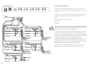
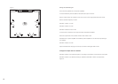
Set Bank 2 Switches 2 & 3 according to the number of filters required.
Set the P (all) gain control (C3) to zero.
The markings on the filter control dials are approximate and for guidance only.
Set the individual filter gain controls (C4, C7 & C10) to -14dB
Set the individual filter Q controls (C5, C8 & C11) to approximately 4.
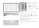
This enables the centre frequency response of the filters to be readily seen.
Set the individual filter frequency controls (C6, C9, C12) initially to 500Hz. This keeps the filters
away from the frequency range of interest until they are tuned one at a time to compensate the
frequency response.
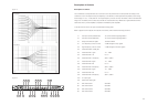
Turn the filter frequency controls (C6, C9 & C12) to the centre frequencies of the peaks or dips to be
equalised. This is an approximate initial setting.
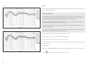
Take repeated frequency response measurements to see the effects of the adjustments you are
about to make. Every now and then you may wish to discard plots and this may be done by
unchecking those you do not need on the plot list to the right of the screen.
Adjust the filter centre frequencies until the measured dips in the response line up accurately with
the centres of the peaks or dips originally in the response.
Adjust the filter gain controls (C4, C7 & C10) so that the response at the centre frequency of each
filter is at the target level (the desired smoothed level).
Lower the filter Q controls (C5, C8 & C11) to broaden the range of the filters until the response is as
smooth as possible.
The controls are to some extent interactive and it may be worthwhile going round the loop of
checking the control settings a second time.
25
Altering the parametric filter controls is likely to also affect the overall gain of the subwoofer and LF
sections. To restore the correct levels:
• Switch off all power amplifiers to avoid the danger of overloading the drive units.
• Disconnect the sound card from the test input socket.
• Connect the signal generator to the relevant test input socket and set the output to give a 1kHz
sine wave at a level of 1V.
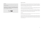
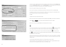
• One or other of the two output indicator lights (T3) will probably be lit. If it is the left one,
turn the parametric filter overall gain (C3) anti-clockwise until both lights are out. Conversely, if
the right light is lit, turn the control clockwise until both lights are out.
Disconnect the signal generator and reconnect the sound card and outputs to the power amplifiers.
Taking further measurements to check the results, adjust the low- and high-frequency controls to
suit.
Additional response shelving up to 40Hz may be achieved by altering the subwoofer gain (C14) and
from 40Hz to 500Hz by altering the LF gain (C13).
If you need to equalise another speaker, you must reload the CT800 setup within WinMLS
and repeat the above process.