


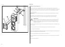
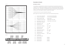
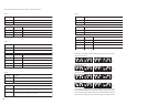

CT8 XO rear panel
ON
Front left/right channels
ON
Left surround channel
ON
Right surround channel
ON
Centre channel
Figure 18
CT8 XO rear panel
ON
Front left/right channels
ON
Left surround channel
ON
Right surround channel
ON
Centre channel
Figure 18
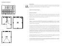
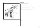
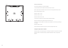
The CT8 XO crossover/equaliser
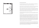
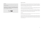
The CT8 XO may be placed on a table or shelf or in a 19-in rack. If housed in an
enclosed structure, proper ventilation must be supplied as stated in the in the safety
instructions.
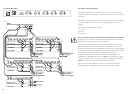
The CT8 XO is connected between the surround processor and the power amplifiers.
A choice of unbalanced (cinch / RCA Phono) or balanced (XLR) connectors is
provided.
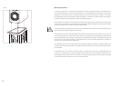
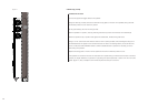
The wiring convention for XLR connectors is:
Pin 1: Ground
Pin 2: Live
Pin 3: Return
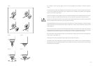
For each CT8 XO setup, use only all balanced or all unbalanced connections.
Mixing the type of connectors could lead to a severe tonal imbalance in the system
depending on the other equipment used in the installation.
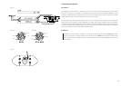
If 12V trigger switching of the dispersion mode (monopole/dipole) of the CT8 DS
surround speakers is required, the assigned 12V trigger output from the surround
processor is connected to the 12V TRIGGER IN of one of the CT8 XO units assigned
to a CT8 DS. The other CT8 XO trigger inputs are connected daisy chain fashion from
the TRIGGER LOOP socket of one to the TRIGGER IN of the next. The
TRIGGER OUT sockets are connected to the relevant CT8 DS speakers. The
TRIGGER IN and TRIGGER LOOP sockets are mono 3.5mm jacks with the positive
(12V) wire connected to the tip of the plug, whereas the TRIGGER OUT socket is a
stereo 3.5mm jack on both the CT8 XO and CT8 DS loudspeaker.
Figure 18 shows the wiring diagram of a typical 5.1 CT800 system having two
CT8 SW speakers, one assigned to each of the front left and right channels.
The CT8 XO Rear Panel
16