


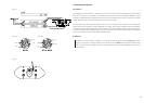

Description of controls
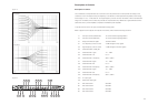
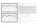
The unit features a comprehensive set of controls to tune the performance of each speaker according to the
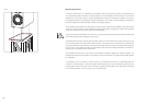
conditions of use. The response may be shaped by a combination of three parametric equalisers, each having
a level range of +4.5 / -12 dB, and low- and high-frequency contour controls, the effects of which are illustrated
in figure 19. In addition, level controls are provided to compensate for any differences in gain between both the
subwoofer and LF power amplifiers compared to the MF/HF power amplifier.
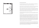
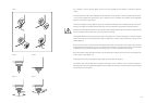
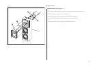
To access the front of the unit, pull off the decorative facing plate.
Description of Controls
LF Contour
HF Contour
Figure 19
17
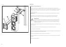
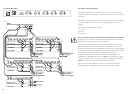
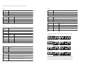
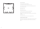
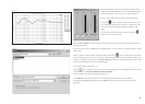
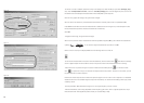
Refer to figure 20 for the layout of the inputs and controls, which have the following functions:
T1 Test input socket (unbalanced) To connect external signal generator
T2 Test input socket (balanced) To connect external signal generator
T3 Output level indicator lights To balance levels
C1 Low-frequency contour control ± 6dB see figure 19 top graph
C2 High-frequency contour control ± 4dB see figure 19 bottom graph
C3 Parametric filters-overall gain
C4 Parametric filter 1-gain +4 / -12dB
C5 Parametric filter 1-Q 0.5 - 5
C6 Parametric filter 1-frequency 30Hz - 500Hz
C7 Parametric filter 2-gain +4 / -12dB
C8 Parametric filter 2-Q 0.5 - 5
C9 Parametric filter 2-frequency 30Hz - 500Hz
C10 Parametric filter 3-gain +4 / -12dB
C11 Parametric filter 3-Q 0.5 - 5
C12 Parametric filter 3-frequency 30Hz - 500Hz
C13 LF output gain
C14 Subwoofer output gain
S1 DIP switch bank 1 See table
S2 DIP switch bank 2 See table
S3 DIP switch bank 3 See table
S4 DIP switch bank 4 See table
Figure font: Helv 45, 7pt
Figure spacing: 7 x 7 mm
Figure 20
Figure 21
T1 T2 T3
C1 C2
C3
C4 C5 C6
C7 C8 C9
C10 C11
C13
C12
C14
S1 S4S2
S3
+
+
+
+
Figure 20