


14 1939STB4600 Manual
B&B Electronics Mfg Co Inc – 707 Dayton Rd - PO Box 1040 - Ottawa IL 61350 - Ph 815-433-5100 - Fax 815-433-5104
B&B Electronics Ltd – Westlink Commercial Park – Oranmore, Galway, Ireland – Ph +353 91 792444 – Fax +353 91 792445
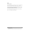
Message Header Setup
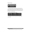
Before a message can be sent to the SAE-J1939 bus, the message header
must be configured to direct the data correctly. The following table shows the
bytes that must be set to direct a message to the SAE-J1939 bus.
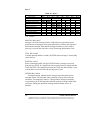
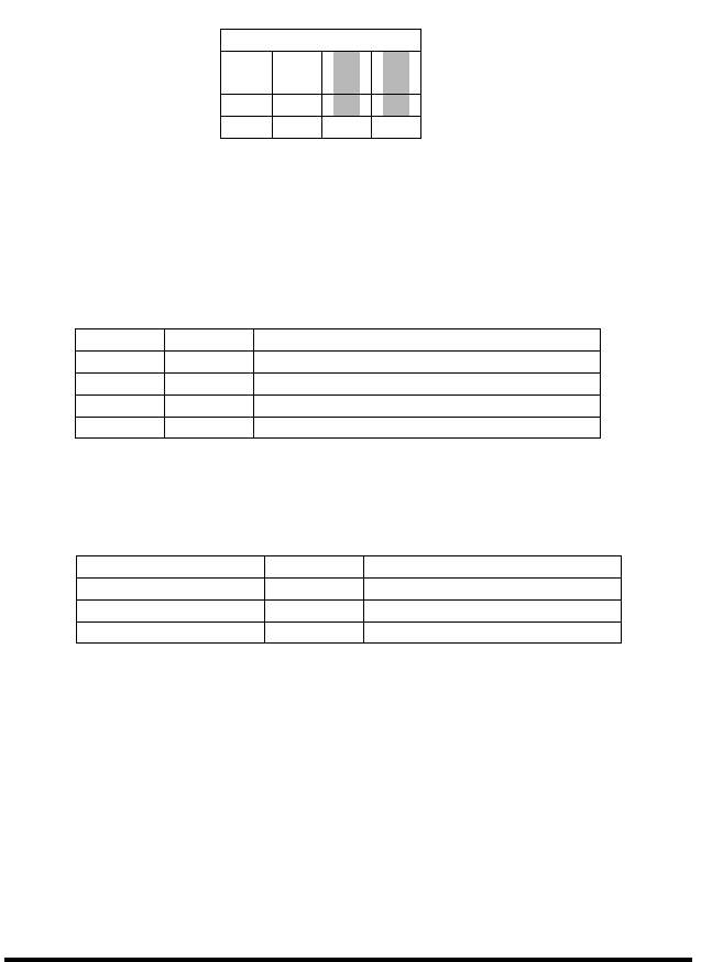
The first two bytes are for the start of message. The third byte (B3)
containing hex 1F,1 directs the message to the J1939 bus. (F) hex is the
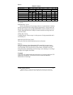
number of bytes in the payload. Byte four (B4) tells the converter in which
message slot to put the message (slot 5). Valid slots are 1 through 15, but slot
15 is reserved for receive only.
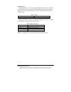
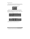
Table 21. Valid Codes for Byte 4
Function Nibble 2 Nibble 1
No function (reserved) Value = 0
Message slot number Value = 1 to 15 (1 to F hex)
Each message must have a unique slot number. A message sent
to the same slot number overwrites the previous message.
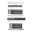
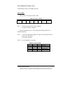
Table 19. J1939 Message Header
Message Header
B
1
B
2
B
3
B
4
81 21 1F 05
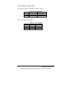
Table 20. Valid Codes for Byte 3
Nibble 2 Value Function
1 Message directed to SAE-J1939 bus
2 Internal commands, vender #, baud change
Nibble 1
0 to 15 Number of bytes to follow byte 4