


1939STB4600 Manual 3
B&B Electronics Mfg Co Inc – 707 Dayton Rd - PO Box 1040 - Ottawa IL 61350 - Ph 815-433-5100 - Fax 815-433-5104
B&B Electronics Ltd – Westlink Commercial Park – Oranmore, Galway, Ireland – Ph +353 91 792444 – Fax +353 91 792445
Description
The 1939STB is an interface device allowing the user to connect a PC to
an SAE-1939 bus via a serial port. The 1939STB conforms to the Physical
Layer specification as set forth in SAE-J1939/11. The 1939STB allows the
reception and transmission of messages over an SAE-J1939 standard bus.
This converter has 14 message “slots” that can be configured for either
reception or transmission. A sample program is provided to aid in the setup
of the interface. Source code is provided and can be found in a subdirectory
under B&B Electronics/J1939/VB6. The Visual Basic program runs under
Windows: however, setup and data transfers can be sent and received by any
terminal capable of serial communications.
The power supply is a wide-range design and will accept a DC voltage
between 10 and 42 volts. The 1939STB has reverse polarity protection.
Power is connected to the 1939STB though a terminal block located under
the snap cover. +DC is connected to the terminal marked “POWER”. -DC is
connected to the terminal marked “GND”.
The serial port on the 1939STB is a 9-pin male connection, configured as
DCE (pin 2 receive// pin 3 transmit). The serial baud rate is user selectable
between 300 and 57600. The stop, parity, and word length can also be
adjusted.
Two LED’s are provided on the 1939STB. One indicates that DC power
is connected to the converter and the power supply is working properly. This
LED will be lit constantly. The second LED is labeled “DATA”. This LED
monitors the function of the converter. After the device is connected, the
LED should flash approximately once every 2 seconds. The flashing LED
confirms that the converter is operating properly and is ready to accept data.
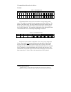
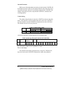
Connection to the SAE-J1939 bus is made by a terminal connection. The
terminal, located under the snap cover, is marked “CAN LOW and “CAN
HIGH”. In some applications it may be necessary to add a terminating
resistor across the CAN high/low terminals. Consult the SAE-J1939/11
publication for details concerning terminating resistors.
The terminals marked “ A” and “B” are not used.