


6 1939STB4600 Manual
B&B Electronics Mfg Co Inc – 707 Dayton Rd - PO Box 1040 - Ottawa IL 61350 - Ph 815-433-5100 - Fax 815-433-5104
B&B Electronics Ltd – Westlink Commercial Park – Oranmore, Galway, Ireland – Ph +353 91 792444 – Fax +353 91 792445
Control Byte 3
Byte 3 directs the data packet to the proper destination. The setting of
this byte will affect the rest of the message. That is to say changing this byte
changes the meaning of the following data bytes.
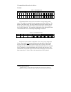
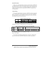
Byte 3 has two parts, Nibble 1 and Nibble 2. Nibble 2 (bits 4 – 7) sets
the control code as follows:
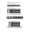
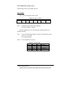
Nibble 1 (bits 0 – 3) of control byte 3 defines the number of bytes in the
data payload of the message. The byte count does NOT include the message
header (bytes 1 through 4). The message payload is limited to 16 bytes. This
limit allows a complete J1939 packet to be sent or received from the bus.
Nibble 1 of control byte 3 can be set to any value between 0 and 16
(0 to F hex).
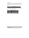
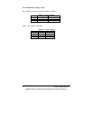
Table 3. Bits of Byte 3
Nibble 2 Nibble 1
Bit 7 Bit 6 Bit 5 Bit 4 Bit 3 Bit 2 Bit 1 Bit 0
Table 4. Byte 3 Nibble 2
Bit Number Value Function
1 Reserved not used Bit 7
0 Reserved not used
1 Reserved not used Bit 6
0 Reserved not used
1 Internal commands (Baud rate, Version number) Bit 5
0 No function
1 External commands (Messages to J1939 bus) Bit 4
0 No function
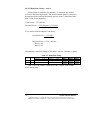
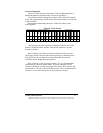
Table 5. Transmit Data Format
Byte 1 Byte 2 Byte 3 Byte 4
Message Information Data Payload
Check
1
Check
2
Control
1
Control
2
<< Count Number of Bytes for byte 3 nibble 1 >>
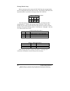
Table 6. Byte 3 Nibble 1
Bit Number Value Function
1 Number of bytes in data payload (MSB) Bit 3
0
1 Number of bytes in data payload Bit 2
0
1 Number of bytes in data payload Bit 1
0
1 Number of bytes in data payload (LSB) Bit 0
0