


1939STB4600 Manual 5
B&B Electronics Mfg Co Inc – 707 Dayton Rd - PO Box 1040 - Ottawa IL 61350 - Ph 815-433-5100 - Fax 815-433-5104
B&B Electronics Ltd – Westlink Commercial Park – Oranmore, Galway, Ireland – Ph +353 91 792444 – Fax +353 91 792445
Communication directed to the device
Format:
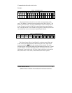
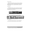
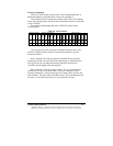
All communications to the device start with a message header (white
area). This header is removed from any message sent to the J1939 bus. The
header is four bytes long. Two bytes (B1& B2) are used to confirm start of
frame. The next two bytes (B3 & B4) contain information controlling how
the 1939STB functions. The remainder of the packet is the data payload and
can contain from zero to sixteen bytes depending on function.
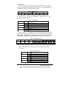
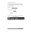
The first two bytes (Check 1 and Check 2) are always set to 81hex and
21hex. These bytes must
precede all data sent to the device. If the Check
bytes are not sent consecutively the message will be rejected. The entire
message must be resent before data can be transmitted to the device. Control
(byte 3 and byte 4) contain information that is used by the converter. This
information is not passed to the J1939 bus. Both control bytes must contain
data (cannot have a value of 00) or the transmission will be rejected.
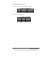
Table 1. J1939STB Format
Message header Message Information Data Payload
B
1
B
2
B
3
B
4
B
5
B
6
B
7
B
8
B
9
B
1
0
B
1
1
B
1
2
B
1
3
B
1
4
B
1
5
B
1
6
B
1
8
B
1
9
B
2
0
8
1
2
1
1
F
0
5
9
5
E
7
0
c
8
0
0
0
4
0
8
c
4
1
4
2
4
3
4
4
4
5
4
6
4
7
4
8
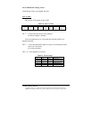
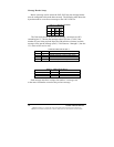
Table 2. Transmit Data Format
Byte 1 Byte 2 Byte 3 Byte 4 Message Information Data Payload
Check
1
Check
2
Control
1
Control
2