


Making Hardware Connections
10 Chapter 2 Manual Documentation Number: ESP901-902_0508m
B&B Electronics Mfg Co Inc – 707 Dayton Rd - PO Box 1040 - Ottawa IL 61350 - Ph 815-433-5100 - Fax 815-433-5104 – www.bb-elec.com
B&B Electronics Ltd – Westlink Commercial Pk – Oranmore, Galway, Ireland – Ph +353 91-792444 – Fax +353 91-792445 – www.bb-europe.com
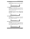
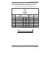
Indicator Lights
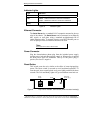
Light Indication
Power
Red - power is applied
Link
Yellow – 10BaseT Ethernet connection established
Green – 100BaseTX Ethernet connection established
Ready
Flashing Green – system is ready
Figure 5. Indicator Lights
Ethernet Connector
The Serial Server has a standard RJ-45 receptacle mounted in the top
edge of the chassis. The Serial Server can be connected to an Ethernet
hub, switch, or wall plate using a standard straight-through RJ-45
(male) Ethernet cable. To connect directly to an RJ45 Ethernet port on
a PC or laptop a crossover Ethernet cable must be used.
N
N
o
o
t
t
e
e
:
:
Refer to Appendix D for details on Network Cables
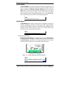
Power Connector
Plug the ultra-miniature phone plug from the included power supply
into the power jack and then plug the supply in. When power is applied
the Red power light will illuminate. The tip of the power plug is
positive; the sleeve is negative.
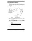
Reset Button
This switch resets the unit, similar to the effect of removing/applying
power. The Reset switch is recessed to avoid accidental operation. To
reset the unit, insert a small plastic tool, press lightly and hold for three
seconds. The Link and Ready lights will go out and then come back on.
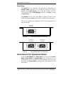
RJ-45
female
Reset
Power jack
2.5 mm Tip (+)
Off
Figure 6. Top View of ESP901 and ESP902 (when mounted vertically)