


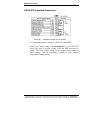

RS-232 Connections
72 Appendix A Manual Documentation Number: ESP901-902_0508m
B&B Electronics Mfg Co Inc – 707 Dayton Rd - PO Box 1040 - Ottawa IL 61350 - Ph 815-433-5100 - Fax 815-433-5104 – www.bb-elec.com
B&B Electronics Ltd – Westlink Commercial Pk – Oranmore, Galway, Ireland – Ph +353 91-792444 – Fax +353 91-792445 – www.bb-europe.com
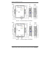
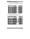
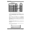
RS-232 Straight-through Cable Connections
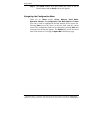
In the RS-232 mode, the Serial Server’s ports are configured as DTEs
like a computer. If the device connected to the
Serial Server is
configured as a DCE use a straight through cable wired as shown
below:
Figure 61. Straight-through DB-9 to DB-9 RS-232 Serial Cable
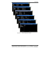
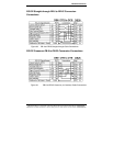
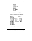
RS-232 Crossover (null modem) Cable Connections
When connecting to a PC or another DTE device, use a crossover cable
(also called a null modem cable).
Figure 62. Crossover DB-9 to DB-9 RS-232 Serial Cable
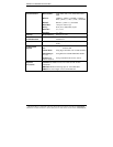
RS-232 Signal Names DB-9
Pin#
Connections DB-9
Pin#
Signal
Carrier Detect CD 1 1 CD
Receive Data RD 2 2 RD
Transmit Data TD 3 3 TD
Data Terminal Ready DTR 4 4 DTR
Signal Ground/Common GND 5 5 GND
Data Set Ready DSR 6 6 DSR
Request to Send RTS 7 7 RTS
Clear to Send CTS 8 8 CTS
Ring Indicator RI 9 9 RI
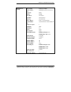