


Making Hardware Connections
12 Chapter 2 Manual Documentation Number: ESP901-902_0508m
B&B Electronics Mfg Co Inc – 707 Dayton Rd - PO Box 1040 - Ottawa IL 61350 - Ph 815-433-5100 - Fax 815-433-5104 – www.bb-elec.com
B&B Electronics Ltd – Westlink Commercial Pk – Oranmore, Galway, Ireland – Ph +353 91-792444 – Fax +353 91-792445 – www.bb-europe.com
Serial Ports
The ESP901 has one serial port. The port can be configured as a
Console Mode connection or as an RS-232, RS-422 or RS-485
interface to the
Serial Server (if any of the DIP switches are in the
OFF position) using the
ESP Manager software, via Telnet, or using
the
Web Server.
The
ESP902 has two serial ports. Port 1 operates the same as the
ESP901 serial port.
Port 2 on the ESP902 is an RS-232 only interface.
The RS-232 interfaces are configured as DTEs. The connectors for all
ports are DB-9M.
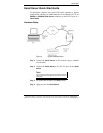
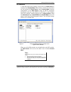
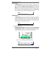
Serial Port
DB-9 Male
Figure 8. The ESP901 Serial Port Connector
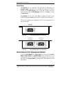
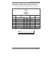
Serial Port 1
DB-9 Male
Serial Port 2
DB-9 Male
Figure 9. The ESP902 Serial Port Connectors
Serial Server/Port Operational Modes
Using the ESP Manager the Serial Server can be put into Console
Mode, Default Mode
or Upgrade Mode. The serial ports can be
configured for RS-232, RS-422 or RS-485 operation. The server also
can be put into
Console Mode by placing all the DIP switches into the
ON position.