


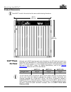
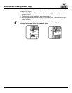
Connecting (Cabling) Each MVP™
MVP™ (12/18/37.5) Series Getting Started User Manual, Rev. 10 -13-
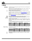
Connecting the
Signal Input
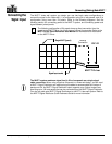
The MVP™ video wall system you design can use two basic setup configurations to
connect the signal to the video wall: (1) a configuration using 24 or less panels, and (2) a
configuration using more than 24 panels. Refer to the following diagrams. See the
following section for connecting power to the MVP™ system, and connecting power and
signal between joined panels.
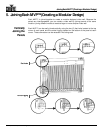
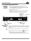
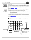
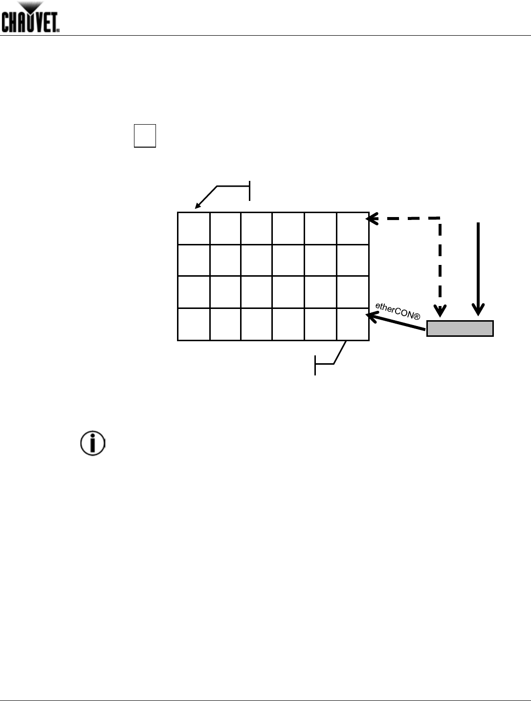
The following configuration of 24 panels shows a direct connection from the
signal to the MVP™ Driver into the first panel’s Signal Input socket. Refer to the
MVP™ Driver Quick Reference User Manual for information and instructions
on the MVP™ Driver.
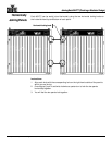
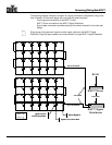
The MVP™ system maximum signal load is 24 or less panels on a single signal
cable connection. When using more than 24 panels in a video wall design, you will need
a MVP™ Signal Distributor and additional signal cables to accommodate the number of
panels over 24. An MVP™ Signal Distributor output supports up to 8 signal output lines,
providing up to 192 total panels that can be connected from the MVP™ Signal Distributor.
You also can add more MVP™ Signal Distributors to a MVP™ video wall system. Refer to
the MVP™ Signal Distributor Quick Reference Guide for more information.
Single MVP™ (panel)
1
Signal Input socket
MVP™ Driver
DVI-D
Backup
Connection