


Connecting (Cabling) Each MVP™
-14- MVP™ (12/18/37.5) Series Getting Started User Manual, Rev. 10
Connecting
Power and
Signal Cables
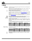
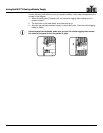
The following sections provide information and diagrams on connecting signal and power
between panels.
One Neutrik® etherCON® signal cable and one Neutrik® powerCON® power cable are
included with each MVP™ package—one cable of each kind per MVP™ in the package.
These cables are to be used for panel linking only. You are able to purchase additional
cables.
Refer to the Introduction or Operation sections in this User Manual for available cables
and item numbers.
Connecting
the Signal
Between
Joined Panels
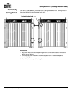
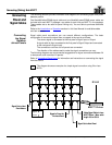
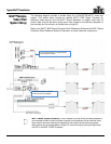
Signal cable panel connections can use several different configurations.
The basic
configuration to connect the signal from one panel to the next is as follows.
· The source signal is connected to the first panel’s Signal Input or Output.
· A signal cable is then connected to the first panel’s Signal Output and connected
to the next panel’s Signal Input.
· The connections continue until all panels are connected.
· The direction of the cables used to make the signal connections can vary.
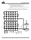
The following diagrams are recommended suggestions for signal connections between 24
or less panels, and more than 24 panels.
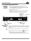
Refer to Connecting Signal Input for information and instructions on connecting the signal
from the source.
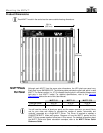
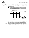
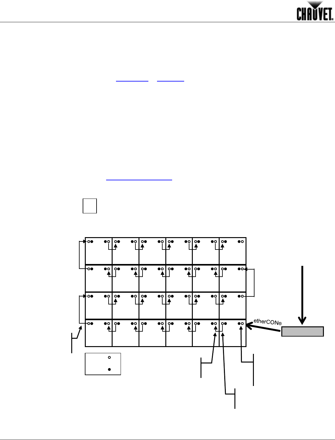
This diagram shows an example of a simple signal connection using 24 or less
MVPs.
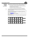
Signal Out to Next
Panel Above
Signal
Power
MVP™ Driver
DVI-D
Video Signal Cable in from
MVP™ Driver – Max. cable
length 100 m/328 ft
Signal Out to Next Panel
Signal In From the
Previous Panel
1