


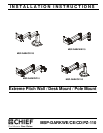
Installation Instructions MSP-DARKWE/CE/CD/PZ-110
7
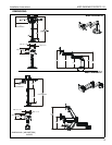
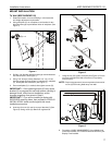
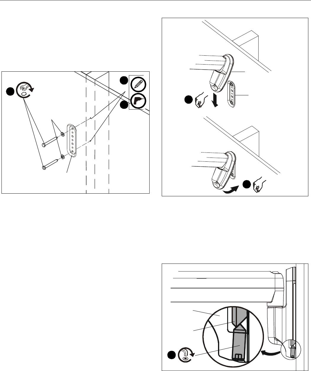
MOUNT INSTALLATION
To Wall (MSP-DARKWE110)
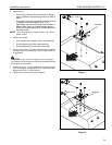
1. Determine location for mount keeping in mind extension
and height adjustment requirements.
2. Using wall plate (C) as a template, mark location for two
pilot holes through top and bottom holes of wall plate. (See
Figure 1)
Figure 1
3. Drill two 1/8” diameter pilot holes through marked locations
into wall structure. (See Figure 1)
4. Using 7/16” wrench, loosely install two 1/4” x 2 1/2” hex
head lag screws (D) through two 1/4” washers (E), wall plate
(C), and drywall into wood stud. (See Figure 1)
5. Ensure wall plate (C) is vertical, then tighten screws (D).
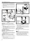
IMPORTANT ! : Over-tightening screws (D) may cause
bracket (C) to compress into soft wall surface, resulting in
damage to wall, difficult mount installation, and/or
improper engaging of set screw in Step 6.
IMPORTANT ! : If you will be installing a display with
RECESSED mounting holes, then proceed to “DISPLAY
INSTALLATION” before continuing with this mount
installation procedure.
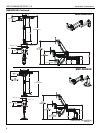
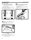
6. Insert top of mount (A) over lip on top of bracket (C) (See
Figure 2). Swing mount (A) down flush against wall.
Figure 2
7. Using hex key (R), tighten set screw (See Figure 3). Ensure
set screw engages back side of bracket (C) to properly
secure mount.
NOTE: Proper engagement of set screw prevents lower end of
mount (A) from being tilted away from wall.
Figure 3
8. Proceed to “CABLE MANAGEMENT” if your display was
previously installed, or to “DISPLAY INSTALLATION” if your
display is not installed.
2
4
3
(D) x 2
(C)
(E) x 2
5
C
5
A
6
C
A