


Installation Instructions MSP-DARKWE/CE/CD/PZ-110
9
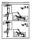
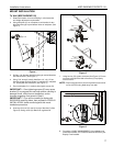
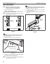
2. Select spacers:
• If mounting holes are flush with back of display,
then no spacers are required; proceed to Step 3
below.
• If mounting holes are recessed into back surface
of display, then place spacer (N or P, as
applicable) over each mounting hole on back of
display (See Figure 8). Select shortest spacer
which will provide adequate fill. All spacers must
be same length.
NOTE: 100 x 100 mounting hole pattern shown; 75 x 75mm
pattern similar.
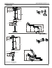
3. Select screw length:
• If no spacers are required, then use screws (K).
• If using spacers (N), then use screws (L).
• If using spacers (P), then use screws (M).
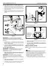
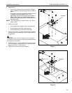
4. Orient mount (A, B or V) so that mounting holes in faceplate
are aligned with holes in display or holes in spacers (M, N),
as applicable.
CAUTION: Using screws of improper size may damage
your display! Proper screws will easily and completely thread
into display mounting holes.
5. Install screws (K, L, or M; as applicable) through mounting
holes on faceplate and spacers (N or P, if applicable) into
display (See Figure 7) (See Figure 8).
6. Tighten all four screws. Do not over-tighten!
Figure 7
Figure 8
5
Faceplate
(K, L or M) x 4
x 4
5
(N, P) x 4
2
Faceplate