


44
Front To Back Leveling
The front to back pitch of the deck is normally
determined by the deck wheels when the deck is
operated as designed with its wheels on the ground.
However, the deck pitch should be checked to ensure
an even cut when mowing uneven terrain, or when
mowing with the deck wheels off the ground.
When properly leveled, the pitch of the deck will result
in the front and rear cutting edges of the blades being
even, to a maximum of 1/4 inch lower in the front.
The front to back pitch of the deck was initially set
when adjustment of the deck hanger rod assembly
was completed during deck installation and should be
within specifications. Check and, if necessary, adjust
the pitch of the deck as follows:
NOTE: Check for proper tire inflation before checking
and/or making a leveling adjustment.
• Use the tractor hydraulic lift system to raise the
deck so that its wheels are off the ground. Stop
the engine.
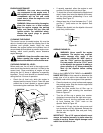
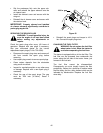
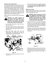
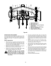
• Carefully rotate the outer cutting blades so that
the ends of the blades point to the front and rear
of the deck. See Figure 56.
NOTE: If side to side leveling of the deck was
correctly performed, measuring only the right
blade should be adequate to check the front to
back leveling.
Figure 56
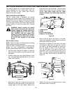
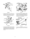
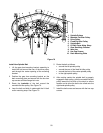
• Accessing the right hand blade through the
discharge chute opening, measure the distance
from the front cutting edge to the ground
(measure A), and from the rear cutting edge to
the ground (measure B). The front edge of the
blade (measure A) should be between equal with
its back edge (measure B) and lower by a
maximum of 1/4 inch. See Figure 57.
Figure 57
• If the measurements are not within this range, the
front to back leveling of the deck should be
adjusted as follows:
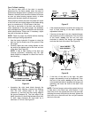
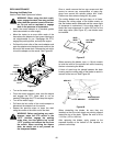
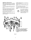
• If the front of the deck is too low, the deck hanger
rod assembly must be shortened. From the front
of the tractor, evenly turn the hex lock nuts
clockwise to shorten the hanger rod assembly
and raise the front of the deck. See Figure 58.
Figure 58
• If the front of the deck is too high, the deck
hanger rod assembly must be lengthened. From
the front of the tractor, evenly turn the hex lock
nuts counterclockwise to lengthen the hanger rod
assembly and lower the front of the deck. See
Figure 58.
NOTE: The front hanger rod must be against the front
of both slots in the deck front roller bracket. If one
side of the rod is not against the front of the slot after
attaining the correct front pitch to the deck, tighten the
front lock nut on that side until the rod just contacts
the front of the slot.
RIGHT BLADE POINTING
TO FRONT AND REAR
CHUTE
DEFLECTOR
A
B
FRONT
CUTTING
EDGE
REAR
CUTTING
EDGE
HEX LOCK NUT
DECK HANGER
ROD ASSEMBLY