


45
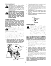
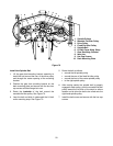
SETTING THE CUTTING HEIGHT
The deck cutting height is set by positioning the left
and right caster wheel axles in one of the five index
hole settings of the deck height adjustment bracket.
The index hole settings range in 1/2 inch increments
from a cutting height of approximately 1-1/2 inches
(top hole) to 3-1/2 inches (bottom hole). If a higher
cutting height is desired, the deck will have to be
suspended from the tractor’s lift system. Use the
system’s lift lever to set the deck cutting height. The
caster wheels will not contact the ground.
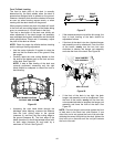
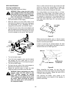
Refer to Figure 59 and adjust the deck cutting height
as follows:
WARNING: Use caution adjusting the
deck height if the deck’s weight is not
supported by the tractor lift system.
Removal of the fasteners securing the
caster wheel axles could allow the deck
to drop and may result in minor injury.
• Use the tractor lift system to raise the mower
deck off the ground.
• Working from either the left or right hand side of
the deck, support the caster wheel axle and
remove the two carriage bolts and hex lock nuts.
See Figure 59.
• Align the caster wheel axle with two
corresponding lower index holes to raise the
cutting height, or corresponding upper holes to
lower the cutting height. See Figure 59.
Figure 59
• Insert the two carriage bolts and secure with the
hex lock nuts.
• Repeat the above steps for the caster wheel axle
on the other side of the deck. Make certain the
corresponding index hole setting is used in all
four hole sets.
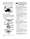
REMOVAL OF DECK
Place the tractor and mower deck on a firm and level
surface with enough room to slide the deck out from
under the right side of the tractor.
WARNING: Before removing the mower
deck, engage the parking brake lever and
turn ignition key to the “OFF” position.
ALWAYS stop the engine after utilizing
the tractor hydraulic lift system. When
handling the mower deck, be careful not
to cut yourself on the sharp blades.
• Check that the deck is in the lower cutting height
position. If it is not, raise the deck, remove the
hex lock nuts and carriage bolts, and reposition
the caster wheel axles in the lower cutting height
position (Refer to Figure 59). Lower the deck to
the ground and stop the engine.
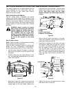
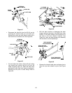
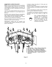
• Compress the locking collar and disconnect the
deck drive shaft from the tractor PTO shaft (See
Figure 60). Pivot the drive shaft to the side as far
as possible.
Figure 60
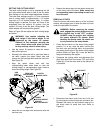
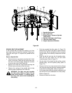
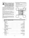
• Disconnect the check chain from the LH lift arm
by removing the internal cotter pin and clevis pin.
Reinstall the clevis pin and internal cotter pin in
the check chain to avoid their loss. Refer to
Figure 61.
DECK HGT.
ADJUSTMENT
BRACKET
CASTER
WHEEL AXLE
LOWEST
HIGHEST
HEX
LOCK
NUTS
CUTTING HEIGHT
CUTTING HEIGHT
CARRIAGE
BOLTS
PTO SHAFT
LOCKING COLLAR
DRIVE
SHAFT