


CP-520/520A/520F Service Manual
DTV R&D Europe
21
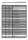
4.1.4 FEATURES
Analogue Video Processing (all versions)
· Multi-standard vision IF circuit with alignment-free PLL demodulator
· Internal (switchable) time-constant for the IF-AGC circuit
· Switchable group delay correction and sound trap (with switchable centre frequency) for the
demodulated CVBS signal
· DVB/VSB IF circuit for preprocessing of digital TV signals.
· Video switch with 3 external CVBS inputs and a CVBS output. All CVBS inputs can be used as
Y-input for Y/C signals. However, only 2 Y/C sources can be selected because the circuit has 2
chroma inputs. It is possible to add an additional CVBS(Y)/C input (CVBS/YX and CX) when the
YUV interface and the RGB/YPRPB input are not needed.
· Automatic Y/C signal detector
· Adaptive digital (4H/2H) PAL/NTSC comb filter for optimum separation of the luminance and the
chrominance signal.
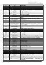
· Integrated luminance delay line with adjustable delay time
· Picture improvement features with peaking (with switchable centre frequency, depeaking,
variable positive/negative peak ratio, variable pre-/overshoot ratio and video dependent coring),
dynamic skin tone control, gamma control and blue- and black stretching. All features are
available for CVBS, Y/C and RGB/YPBPR signals.
· Switchable DC transfer ratio for the luminance signal
· Only one reference (24.576 MHz) crystal required for the TCG m-Controller, digital sound
processor, Teletext and the colour decoder
· Multi-standard colour decoder with automatic search system and various “forced mode”
possibilities
· Internal base-band delay line
· Indication of the Signal-to-Noise ratio of the incoming CVBS signal
· Linear RGB/YPBPR input with fast insertion.
· YUV interface. When this feature is not required some pins can be used as additional
RGB/YPBPR input. It is also possible to use these pins for additional CVBS (or Y/C) input
(CVBS/YX and CX).
· Tint control for external RGB/YPBPR signals
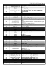
· Scan Velocity Modulation output. The SVM circuit is active for all the incoming CVBS, Y/C and
RGB/YPBPR signals. The SVM function can also be used during the display of teletext pages.
· RGB control circuit with ‘Continuous Cathode Calibration’, white point and black level off-set
adjustment so that the colour temperature of the dark and the light parts of the screen can be
chosen independently.
· Contrast reduction possibility during mixed-mode of OSD and Text signals
· Adjustable ‘wide blanking’ of the RGB outputs
· Horizontal synchronization with two control loops and alignment-free horizontal oscillator
· Vertical count-down circuit
· Vertical driver optimized for DC-coupled vertical output stages
· Horizontal and vertical geometry processing with horizontal parallelogram and bow correction
and horizontal and vertical zoom
· Low-power start-up of the horizontal drive circuit
Analogue video processing (stereo versions)
· The low-pass filtered ‘mixed down’ I signal is available via a single ended or balanced output
stage.
Analogue video processing (mono versions)
· The low-pass filtered ‘mixed down’ I signal is available via a single ended output stage
Digital Video Processing (some versions)
· Double Window mode applications. It is possible to display a video and a text window or 2 text