


CP-520/520A/520F Service Manual
DTV R&D Europe
32
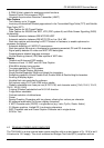
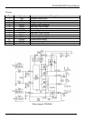
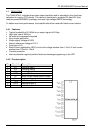
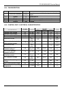
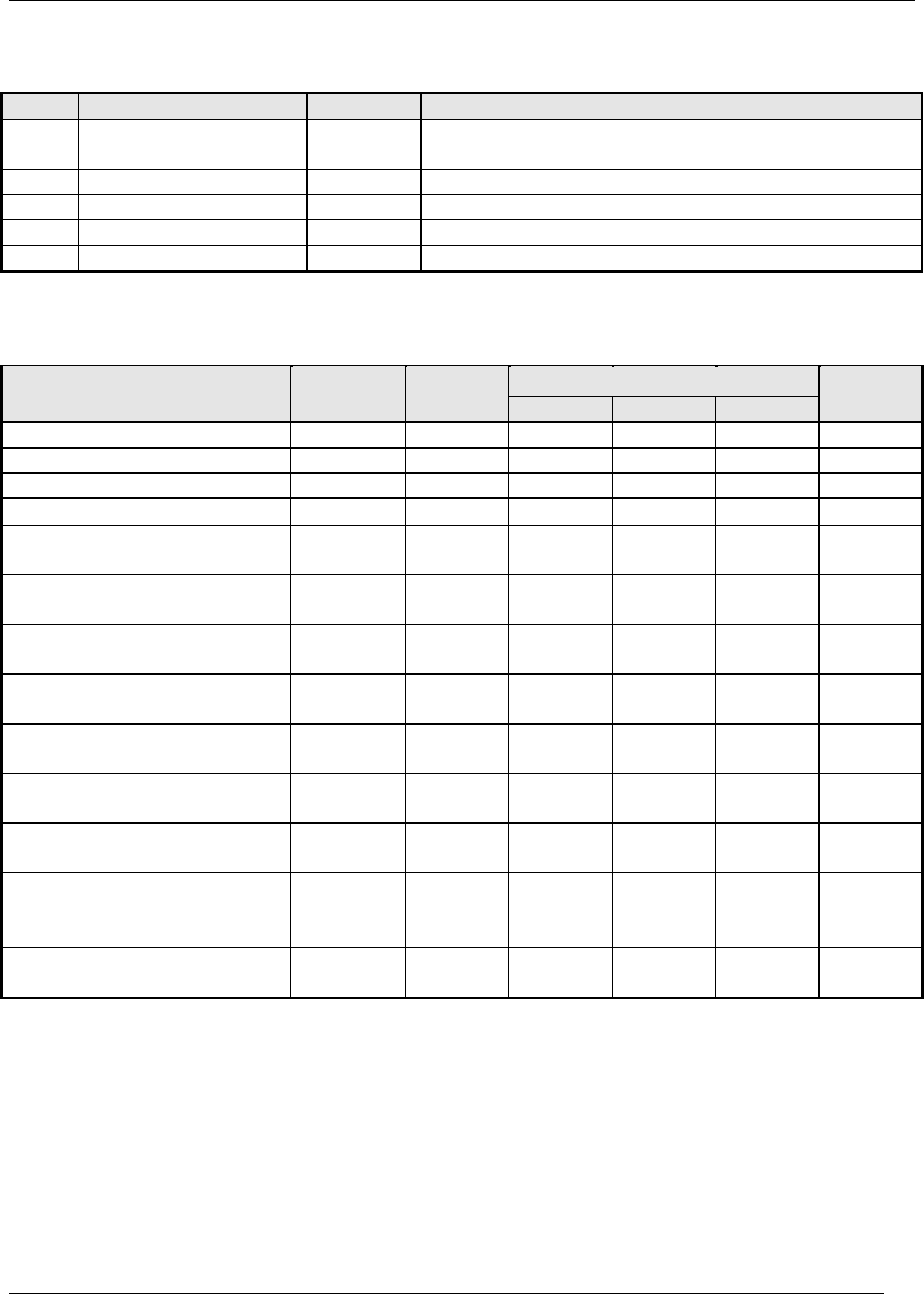
4.6.4 PIN DESCRIPTION
PIN NAME SYMBOL DESCRIPTION
1 Overcurrent feedback
O.C.
P/E.B.
Input of over current detection signal and feedback
signal
2 Source S Mosfet source
3 Drain D Mosfet drain
4 Supply V
IN
Input of power supply for control circuit
5 Ground GND Ground
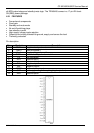
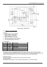
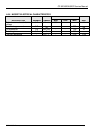
4.6.5 CONTROL PART - ELECTRICAL CHARACTERISTICS
IC PIN RATING
DESCRIPTION NUMBER SYMBOL MIN. TYPE MAX UNIT
Operation start voltage 4-5 V
IN
(on) 14.4 16 17.6 V
Operation stop voltage 4-5 V
IN
(off) 9 10 111 V
Circuit current in operation 4-5 I
IN
(on) - - 30 mA
Circ. current in non-operation
4-5 I
IN
(off) - - 100
µA
Maximum off time
-
T
OFF
(max)
45 - 55
µSEC
Minimum time for input of
quaxi resonant signals
1-5 T
TH
(2) - - 1.0
µSEC
Minimum off time
-
T
OFF
(min)
- - 1.5
µSEC
O.C.P./F.B. terminal
threshold voltage 1
1-5 V
TH
(1) 0.68 0.73 0.78 V
O.C.P./F.B. terminal
threshold voltage 2
1-5 V
TH
(2) 1.3 1.45 1.6 V
O.C.P./F.B. terminal
extraction current
1-2 I
OCP/FB
1.2 1.35 1.5 mA
OVP operation voltage
4-5
V
IN
(OVP)
20.5 22.5 24.5 V
Latch circuit sustaining
voltage
4-5 I
IN
(H) - - 400
µA
Latch circuit release voltage 4-5 V
IN
(Loff) 6.6 - 8.4 V
Thermal shutdown operating
temperature
- T
J
(TSD) 140 - -
0
C