


CP-520/520A/520F Service Manual
DTV R&D Europe
41
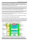
The setting of the gain registers of the 3 channels can be stored during switch off and can be
loaded again during switch-on so that the drive conditions are maintained.
When required the operation of the CCC system can be changed into a one-point black current
system. The switching between the 2 possibilities is realised by means of the EGL bit (EGL = 0)
in subaddress 42H. When used asone-point control loop the system will control the black level of
the RGB output signals to the ‘low’ reference current and not on the cut off point of the cathode.
In this way spreads in the picture tube characteristics will not be taken into account. In this
condition the settings of the “white point control registers”(subaddress 20H-22H) and the
“cathode drive level bits” (CL3 - CL0 in subaddress 42H) are added to the settings of the RGB
preset gain registers (subaddress 23H - 25H).
A black level off-set can be made with respect to the level which is generated by the black
current stabilization system. In this way different colour temperatures can be
obtainedforthebrightandthedarkpartofthepicture.The black level control is active on the Red and
the Green output signal. It is also possible to control the black level of the Blue and the Green
output signal (OFB bit = 1).
In the Vg2 adjustment mode (AVG=1) the black current stabilization system checks the output
level of the 3 channels and indicates whether the black level of the highest output is in a certain
window(WBC-bit) or below or above this window (HBC-bit). This indication can be read from the
status byte 01 and can be used for automatic adjustment of the Vg2 voltage during the
production of the TV receiver. During this test the vertical scan remains active so that the
indication of the 2 bits can be made visible on the TV screen.
The control circuit contains a beam current limiting circuit and a peak white limiting circuit. The
control is realised by means of a reduction of the contrast and brightness control settings. The
way of control (first contrast and then brightness or contrast and brightness in parallel) can be
chosen by means of the CBS bit (subaddress 44H). The peak white level is adjustable via the
I2C-bus.
To prevent that the peak white limiting circuit reacts on the high frequency content of the video
signal a low-passfilter is inserted in front of the peak detector. The circuit also contains a soft-
clipper which prevents that the high frequency peaks in the output signal become too high. The
difference between the peak white limiting level and the soft clipping level is adjustable via the
I2C-bus in a few steps.
During switch-off of the TV receiver a fixed beam current is generated by the black current
control circuit. This current ensures that the picture tube capacitance is discharged. During the
switch-off period the vertical deflection can be placed in an overscan position so that the
discharge is not visible on the screen.
A wide blanking pulse can be activated in the RGB outputs by means of the HBL bit in
subaddress 43H. The timing of this blanking can be adjusted by means of the bits WBF/R bits in
subaddress 26H.
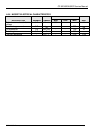
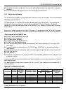
WPR(GB) ‘0’ B5 B4 B3 B2 B1 B0 Max 64
CL ‘0’ B3 B2 B1 B0 ‘0’ ‘0’ Max 60
CCC-gain B6 B5 B4 B3 B2 B1 B0 Max 126
R(GB)-gain B6 B5 B4 B3 B2 B1 B0 Max 126