


CP-520/520A/520F Service Manual
DTV R&D Europe
39
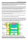
The circuit contains the following picture improvement features:
n Peaking control circuit. The peaking function can be activated for all incoming CVBS, Y/C
and RGB/YPrPb signals. Various parameters of the peaking circuit can be adapted by means
of the I2C-bus. The main parameters are:
- Peaking centre frequency (via the PF1/PF0 bits in subaddress 19H).
- Ratio of positive and negative peaks (via the RPO1/RPO0 bits in subaddress 47H). The
peaks in the direction “white” are the positive peaks.
- Ratio of pre- and aftershoots (via the RPA1/RPA0 bits in subaddress 47H).
n Video dependent coring in the peaking circuit. The coring can be activated only in the low-
light parts of the screen. This effectively reduces noise while having maximum peaking in the
bright parts of the picture.
n Black stretch. This function corrects the black level for incoming signals which have a
difference between the black level and the blanking level. The amount of stretching (A-A in
Fig. 72) and the minimum required back ground to activate the stretching can be set by
means of the I2C-bus (BSD/AAS in subaddress 45H).
n Gamma control. When this function is active the transfer characteristic of the luminance
amplifier is made non-linear.Thecontrolcurvecanbeadaptedbymeans of I2C-bus settings (see
Fig. 74). It is possible to make the gamma control function dependent on the picture content
(Average Picture Level, APL). The effect is illustrated in Fig. 75. Previously this function was
mentioned under the name “white stretch function”.
n Blue-stretch. This circuit is intended to shift colour near ‘white’ with sufficient contrast values
towards more blue to obtain a brighter impression of the picture.
n Dynamic skin tone (flesh) control. This function is realised in the YUV domain by detecting
the colours near to the skin tone.
n Scan-Velocity modulation output. Also the SVM function can be activated for all incoming
CVBS, Y/C and RGB/YPrPb signals. The delay between the RGB output signals and the
SVM output signal can be adjusted (by means of the SVM2-SVM0 bits in subaddress 48H)
so that an optimum picture performance can be obtained. Furthermore a coring function can
be activated. It is possible to generate Scan Velocity Modulation drive signals during the
display of ‘full screen’ teletext (not in mixed mode). Another feature is that the SVM output
signal can be made dependent on the horizontal position on the screen (parabola on the
SVM output).
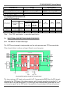
5.2.9 Colour decoder
The ICs decode PAL, NTSC and SECAM signals. The PAL/NTSC decoder does not need
external reference crystals but has an internal clock generator which is stabilised to the required
frequency by using the clock signal from the reference oscillator of the TCG u -Controller.
Under bad-signal conditions (e.g. VCR-playback n feature mode), it may occur that the colour
killer is activated although the colour PLL is still in lock. When this killing action is not wanted it is
possible to overrule the colour killer by forcing the colour decoder to the required standard and to
activate the FCO-bit (Forced Colour On) in subaddress3CH. The sensitivity of the colour decoder
for PAL and NTSC can be increased by means of the setting of the CHSE1/CHSE0 bits in
subaddress 3CH.
The Automatic Colour Limiting (ACL) circuit (switchable via the ACL bit in subaddress 3BH)
prevents that oversaturation occurs when signals with a high chroma-to-burst ratio are received.
The ACL circuit is designed such that it only reduces the chroma signal and not the burst signal.
This has the advantage that the colour sensitivity is not affected by this function.