


CP-520/520A/520F Service Manual
DTV R&D Europe
37
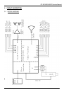
The Ics have 3 inputs for external CVBS signals. All CVBS inputs can be used as Y input for the
insertion of Y/C signals.However, the CVBS(Y)2 input has to be combined with the C3 input. It is
possible to add and extra CVBS(Y/C) input via the pins which are intended to be used for YUV
interface (or RGB/YPrPb input). The selection of this additional CVBS(Y/C) input is made via the
YC bit.
The function of the IFVO/SVO/CVBSI pin is determined by the SVO1/SVO0 bits. When used as
output a selection can be made between the IF video output signal or the selected CVBS signal
(monitor out). This pin can also be used as additional CVBS input. This signal is inserted in front
of the group delay / sound trap circuit. It is also possible to use the group delay and sound trap
circuit for the CVBS2 signal (via the CV2 bit).
For the CVBS(Y/C) inputs the circuit can detect whether a CVBS or Y/C signal is present on the
input. The result can be read from the status register (YCD bit in subaddress 03H) and this
information can be used to put the input switch in the right position (by means of the INA-IND bits
in subaddress 38H). The Y/C detector is only active for the CVBS(Y)3/C3, CVBS(Y)4/C4 and
CVBS(Y)x/Cx inputs. It is not active for the CVBS(Y)2/C3 input.
The video ident circuit can be connected to all video input signals. This ident circuit is
independent of the synchronisation and can be used to switch the synchronisation and can be
used to switch the presence of a video signal (via the VID bit). In this way a very stable OSD can
be realised. The result of the video ident circuit can be read from the output bit SID (subaddress
00).
5.2.6 Synchronisation circuit
The IC contains separator circuits for the horizontal and vertical sync pulses. To obtain an
accurate timing of the displayed picture the input signal of the sync separator is not derived from
the various CVBS/Y or RGB/YPrPb inputs but from the YOUT pin. For this reason the YOUT pin
must be capacitively coupled to the YSYNC pin. The delay between the various inputs and the
YOUT signal can have rather large differences (e.g. comb filter active or not). By choosing the
YOUT signal as input signal for the sync separator these delays have no effect on the picture
position. Only for RGB signals without sync on green the input of the sync separator has to be
connected to one of the CVBS inputs. This selection is made by means of the SYS bit.
The horizontal drive signal is obtained from an internal VCO which is running at a frequency of
25 MHz. This oscillator is stabilised to this frequency by using the clock signal coming from the
reference oscillator of the TCG -Controller.
To obtain a stable On-Screen-Display (OSD) under all conditions it is important that the first
control loop is switched off or set to low gain when no signal is available at the input. The input
signal condition is detected by the video identification circuit. The video identification circuit can
automatically switch first control loop to a low gain when no input signal is available. This mode is
obtained when the VID bit is set to “0”. When the VID bit is “1” the mode of the first control loop
can be switched by means of the FOA/FOB or POC bits.
For a good performance during normal TV reception (display of the front-end signal) various
connections are active between the vision IF amplifier and the synchronisation circuit (e.g. gating
pulses for the AGC detector and noise gating of the sync separator). These connections are not
allowed when external video signals are displayed. The switching of these connections can be
coupled to the input signal selection bits (INA-IND). This mode is obtained when the VDXEN bit
is “0”. Due to the input signal selector configuration it is possible that the internal CVBS signal is