


Installing System Components 131
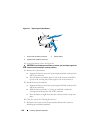
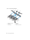
Installing the Control Panel Display Module
1
Insert the display module into the chassis cutout and secure with the two
Torx screws. See Figure 3-22.
2
Attach the replacement panel to the front of the display module.
3
Connect the display module cable to the control panel board.
4
Close the system. See "Closing the System."
5
Reconnect the system to the power source and turn on the system and
attached peripherals.
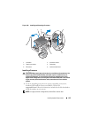
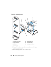
Removing the Control Panel Board
CAUTION: Many repairs may only be done by a certified service technician. You
should only perform troubleshooting and simple repairs as authorized in your
product documentation, or as directed by the online or telephone service and
support team. Damage due to servicing that is not authorized by Dell is not covered
by your warranty. Read and follow the safety instructions that came with the
product.
1
Turn off the system and attached peripherals and disconnect the system
from the electrical outlet and peripherals.
2
Open the system. See "Opening the System."
3
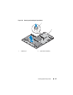
Disconnect the display module cable from the control panel board. See
Figure 3-22.
4
Disconnect the control panel cable and USB cable from the control panel
board. See Figure 3-22.
5
If applicable, disconnect the Internal SD Module cable and remove the
USB key from the control panel module.
CAUTION: Do not pull on the cable to unseat the connector. Doing so can damage
the cable.
6
Using a T8 Torx driver, remove the screw on the front panel located
beneath the left USB connector. See Figure 3-22.
7
Using a T10 Torx driver, remove the three screws that secure the control
panel board to the system chassis and remove the board.