Be d Re d e f i n e R
Op e R a t O R 's Ma n u a l
11
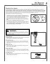
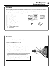
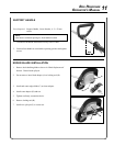
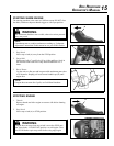
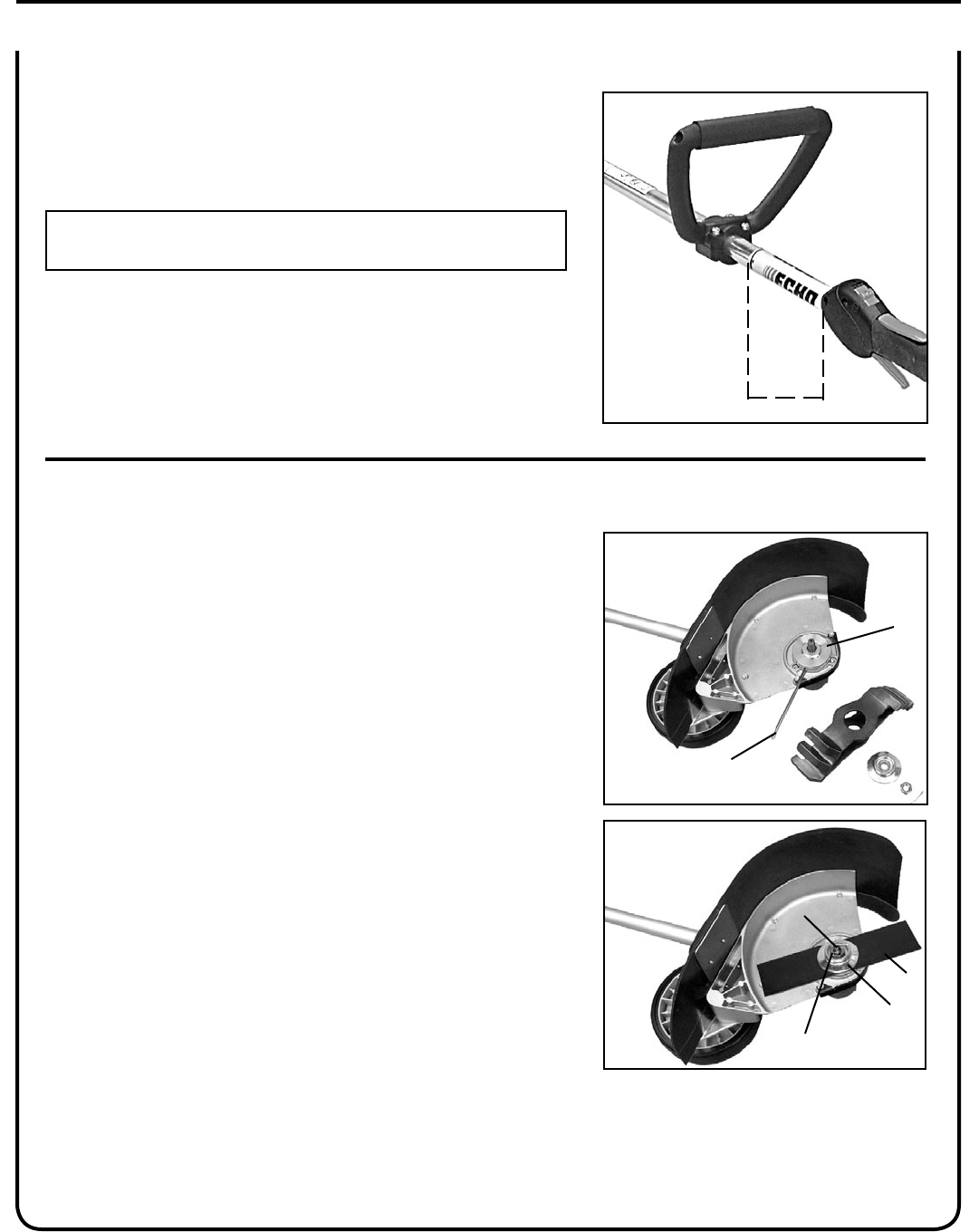
s u p p o r t h a n d l e
Parts Required: Support Handle, Lower Bracket, 4 - 5 x 35 mm
screws
NOTE
Label shows minimum spacing for front handle location.
1. Assemble front handle and bracket loosely to drive shaft.
2. Position front handle in comfortable operating position and tighten
screws.
MIN
SPaCing
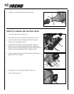
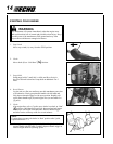
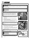
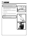
e d g e r b l a d e I n s t a l l a t I o n
1. Remove bed redening blade as shown in “Blade Replacement”
Section. Discard used split pin.
2. Do not remove inner blade adapter (A) or locking tool (B).
3. Install and center edger blade (C) on inner adapter.
4. Install outer adapter (D) and nut.
5. Tighten nut rmly, counterclockwise.
6. Remove locking tool (B).
7. Install new split pin (F) to secure nut.
a
B
F
C
D
E


