


77
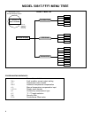
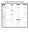
MODEL 5081T-FF/FI WIRING
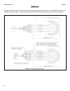
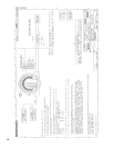
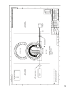
WIRING THROUGH A JUNCTION BOX
The sensor can be wired to the analyzer through a remote junction box (PN 23550-00). Wire the extension cable
and sensor cable point-to-point. Refer to the sensor instruction manual for more details.
Factory-terminated (PN 23747-00) and unterminated (PN 9200275) connecting cable are available. The use of fac-
tory-terminated cable is strongly recommended. To prepare unterminated cable for use, follow the instructions in the
sensor instruction manual.
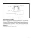
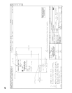
For maximum EMI/RFI protection, the outer braid of the sensor cable should be connected to the outer braided
shield of the extension cable. At the instrument, connect the outer braid of the extension cable to earth ground.
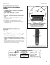
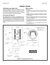
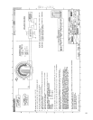
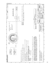
POWER WIRING
For general purpose areas, wire power as shown in Figure 3.
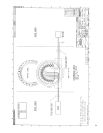
FIGURE 3. Power Supply/Current Loop Wiring for Model 5081T-FF/FI
FOUNDATION FIELDBUS COMMUNICATIONS AND POWER SUPPLY
9 - 32 VDC