


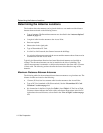

Determining the Antenna Locations
1-4 Site Preparation
RoamAbout PC Card Variations
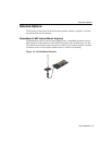
There are two variations of the RoamAbout PC Card: standard and Hi-Gain matched.
The Hi-Gain matched variation of the RoamAbout PC Card is only used when connecting
to a directional antenna in countries that adhere to the European Telecommunications
Standards Institute (ETSI) standards.
All other countries and other configurations use the same standard RoamAbout PC Card.
For example, all countries use the standard RoamAbout PC Card in these configurations:
• PC Card is not connected to an antenna.
• PC Card is connected to a 7 dBi omni-directional antenna.
• PC Card is connected to a vehicle-mount antenna.
Countries that adhere to the Federal Communications Commission (FCC) standards use the
standard RoamAbout PC Card in all configurations.
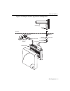
Line of Sight
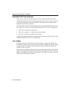
The shape of the radio beam, defined as the Fresnel Zone, is widest in the middle. The
Fresnel Zone is shown as the gray area between the antennas in Figure 1-1. The exact shape
and width of the Fresnel Zone is determined by the distance between the antenna and
frequency of the radio signal.
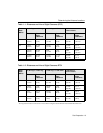
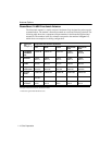
The radius of the radio beam, shown as the lower half of the Fresnel Zone, is the distance
from the center of the beam outward in any direction. The length of the radius is shown in
Table 1-1 and Table 1-2 as the line of sight clearance. The length of the radius is not based
on the data rate and the type of antenna.