Model D2424LVmkII Quick Operation Guide
Initial settings
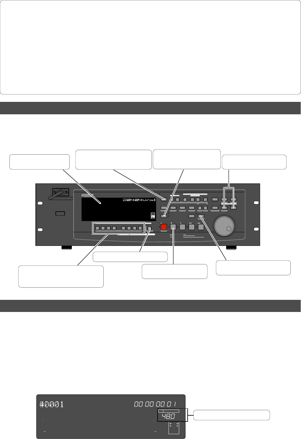
Set all [RECORD TRACK] select keys to
“SAFE.” The track indicators (square
frames) turn off.
Locate the top of the selected
Program (ABS 0).
Turn off the Vari Pitch function. (The
[VARI PITCH] key LED turns off.)
Stop the recorder. (The STOP
button LED turn off.)
Turn off the [TRACK SHIFT] key LED.
Turn off AUTO RTN mode and AUTO
PLAY mode. (AUTO RTN and AUTO
PLAY indicators turn off.)
The [STORE] key and [RECALL]
key LEDs turn off.
Turn off AUTO PUNCH mode.
(The REHEARSAL and TAKE
LEDs go off.)
About Sampling Frequency
You need to reset all the controls on this recorder to their initial settings according to the controls and switches on
the mixer before you proceed to the next step. This procedure is called “Initialize” in this Guide and in the Reference
Manual. The buttons and switches on this recorder should be reset as shown below. Remember to “initialize this
recorder” before you start a new session.
The sampling frequency is important when recording a digital source, as described later in "Basic digital
recording", but is not as important when recording analog source.
As described earlier in "Formatting a hard disk drive", the sampling frequency and quantization of the current
drive (<44.1 kHz 16bit or 24bit>, <48 kHz 16bit or 24bit>, <88.2 kHz 24 bit> or <96 kHz 24bit>) are fixed
when formatting. Therefore, the sampling frequency of a digital device connected to the recorder must match
the recorder's sampling frequency.
In this recorder, the program to be complied in the current drive after formatting can be changed to any
sampling frequency. When several programs recorded using different sampling frequencies are in the cur-
rent drive, sampling frequencies must be confirmed at each change of the program.
<Hints>
• When connecting the recorder to a digital mixing console as shown in the example above, unlike connecting to an
analog console, both digital devices must be synchronized with each other.
To achieve this, use "word clock," the signal for synchronization.
Word clock is used to synchronize all digital words in a system. Normally one digital devices in the system acts as
a master of word clock, and the other devices act as slaves. All the slave devices receive the word clock fed from the
master device and synchronize to it. In the example above, the recorder acts as a word clock master and the digital
mixing console acts as a slave and synchronizes with the recorder. The word clock is fed from the [WORD OUT PUT]
terminal of the recorder to the [WORD INPUT] terminal of the digital mixing console.
• Note that the master word clock setting of the digital mixing console must match the recorder's sampling frequency.
See the instruction manual of the digital mixing console for details.
To execute the digital multitrack recording using a digital mixing console, see "Basic digital recording" on page “18”
for details about the digital multitrack recording using a digital mixing console.
Sampling frequency and quantization.
FSM
∞
42
OL
0
30
24
18
12
9
6
3
kHz
24
FS
BIT
PGM
24
∞
42
OL
0
30
24
18
12
9
6
3
ABS
2322
21
20
19
18
17
1615141312
11
10
98765
4
3
2
1
CLOCK
INT
POWER
HOLD
RECORD
STOP
PLAY
REW
F FWD
ALL INPUT
ALL READY
LOCATE REC END
VARI PITCH
PUNCH
LOCATE
REHEARSAL
TAKE
RECALL
STORE
EXIT/NO
EXECUTE/YES
PGM SEL
NEXT
PREV
UNDO/REDO
PREVIEW
EDIT SETUP
AUTO RTN
OUTIN
AUTO PLAY
START
OUTIN
END
17-24
ACCESS
9-16
1/9/17
2/10/18
3/11/19
4/12/20 5/13/21 6/14/22 7/15/23
8/16/24
FOOT SW
LOCATE ABS 0
CLIPBOARD PLAY
AUTO
TRACK SHIFT
SHIFT
DISP SEL
CHARACTER
TIME BASE SEL
P.EDIT
EJECT
ENVELOPE
CHASE
TC READY TC GEN M.UNDO
TRACK SHIFT
PREV TC
NEXT TC
RECORD TRACK
CLIPBOARD
AUTO PUNCH
AUTO RT N
LOCATE MEMORY
24bit
96kHz
OPTICAL
24TRACK DIGITAL RECORDER
15


