


E-7
EnglishDeutschEspañolFrançaisItalianoPortuguês
日 本 語
Póññêèé
÷–Œƒ
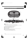
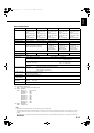
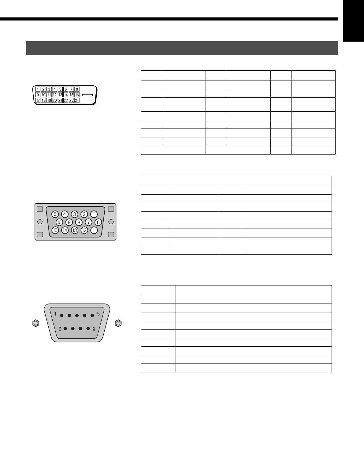
DESCRIPTION OF INPUT TERMINALS
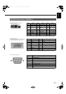
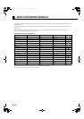
DVI-D terminal (RGB1 INPUT/DVI-D)
for the W/U/A models
Pin No. Signal Pin No. Signal Pin No. Signal
1 T.M.D.S. Data2– 9 T.M.D.S. Data1– 17 T.M.D.S. Data0–
2 T.M.D.S. Data2+ 10 T.M.D.S. Data1+ 18 T.M.D.S. Data0+
3
T.M.D.S. Data2
Shield
11
T.M.D.S. Data1
Shield
19
T.M.D.S. Data0
Shield
4— 12— 20—
5— 13— 21—
6 DDC Clock 14 +5V Power 22
T.M.D.S. Clock Shield
7 DDC Data 15 Ground (for +5V) 23 T.M.D.S. Clock+
8 — 16 Hot Ploug Detect 24 T.M.D.S. Clock–
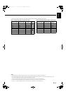
mD-sub input terminal
(RGB2 INPUT/mD-sub) for the W/U/A models
(RGB1 INPUT/mD-sub) for the R model
Pin No. Input signal Pin No. Input signal
1Red 9—
2 Green 10 Ground
3Blue 11—
4— 12—
5 Ground 13 Horizontal synchronization
6 Ground 14 Vertical synchronization
7 Ground 15 —
8 Ground Frame Ground
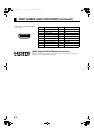
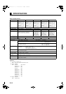
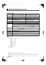
RS-232C terminal (RS-232C)
Pin No. Signal
1 DCD (Data Carrier Detect)
2 RD (Received Data)
3 TD (Transmit Data)
4 DTR (Data Terminal ready)
5 GND (Ground)
6 DSR (Data Set Ready)
7 RTS (Request To send)
8 CTS (Clear To Send)
9 RI (Ring Indication)
MHD01695_E.book 7 ページ 2005年2月1日 火曜日 午後7時7分