


3-9
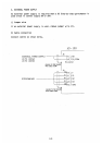
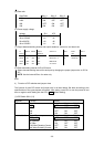
(5) Gear ratio
Gear Ratio SW1-1 SW1-2 SW1-3
X360
X180
X90
X36
OFF OFF OFF
ON OFF OFF
OFF ON OFF
ON ON OFF
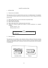
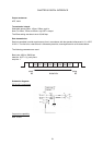
(6) Power supply voltage
Voltage JP4 JP5
20 to 45VAC
30 to 135VAC
20 to 60VDC
40 to 135VDC
#2 #2
#1 #1
#2 #2
#1 #1
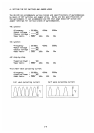
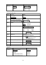
(7) Output data transmitting interval and output sentence, version no. and baud rate.
Tx
interval
SW2-5 SW2-6 Output
sentence
Version no.
SW3-1 Baud
rate
SW3-2
1s
200ms
100ms
25ms
OFF OFF
ON OFF
OFF ON
ON ON
HDT + VHW
HDT
HDT
HDT
NMEA0183 Ver 1.5
IEC61162-1 or
NMEA0183
Ver 2.0/3.0
OFF
ON
4860 bps
38400 bps
OFF
ON
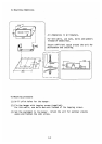
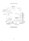
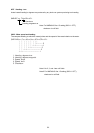
(8) Data transmitting interval of AD-10S format
Select data transmitting interval for each port by changing the proper jumper wire on JP6 or
JP7.
NOTE: Use the interval 25ms. for radar only.
END
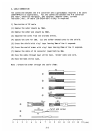
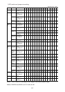
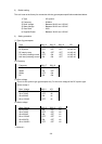
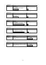
4) Function of DIP switches and jumper wires
The function of each DIP switch and jumper wire is as listed below. Set them according to the
specifications of the gyrocompass connected. After setting, reset CPU or turn the power off and
then on again to write setting into the CPU ( : default setting).
(1) DIP Switch SW1 (1/2)
Segment Function Setting
SW1-1, -2, -3 Gear Ratio
X360
X180
X90
X36
SW1-1 SW1-2 SW1-3
OFF OFF OFF
ON OFF OFF
OFF ON OFF
ON ON OFF
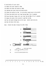
SW1-4, -5, -6 Type of Gyrocompass
AC Synchro
DC Synchro
DC Step
Full Wave Pulsating Current
Half Wave Pulsating Current
SW1-4 SW1-5 SW1-6
OFF OFF OFF
OFF OFF OFF
ON OFF OFF
OFF ON OFF
ON ON OFF