6 598-1116-10
DETECT
CODES
1234
DAY
NIGHT
NIGHT
ONLY
Detect
Control
Battery Compartment
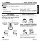
INDOOR AND OUTDOOR
WIRELESS MOTION SENSOR
Features:
• No wiring required.
• Up to 30 feet sensing range, 150° Coverage
(Indoor).
• Up to 70 feet sensing range, 180° Coverage
(Outdoor).
• Adjustable sensitivity.
• Day/Night or Night only operation.
• Test mode.
• Uses 2 AA batteries.
• Can be mounted directly to wall or with
mounting bracket (included) (Indoor).
• Wall or eave mount (Outdoor).
• Controls receivers up to 100 feet away.
O
N
Da
y
/ Ni
g
h
t
N
ight
O
nl
y
5
1
Te
st
Ma
x
Mi
n
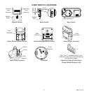
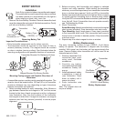
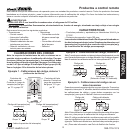
Outdoor Wireless
Motion Sensor
Indoor Wireless
Motion Sensor
CODE
1 2 3 4
ON
5 1 TEST
ON-TIME
(MINUTES)
MIN MAX
DETECT
RANGE
DAY
NIG HT
NIG HT
ONLY
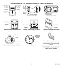
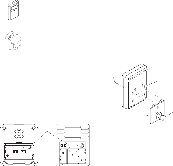
Outdoor Motion Sensor
(Rear View)
Indoor Motion Sensor
(Front View)
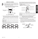
Select Night or 24 Hour Mode
These sensors are able to detect motion day and night or night
only. To set the detection mode, remove battery compartment
cover by sliding the cover down. Remove batteries if necessary.
Slide the DETECT switch to either the DAY/NIGHT or NIGHT
ONLY position. Replace battery compartment cover by reversing
the above instructions.
• Before mounting outdoor motion sensor, remove battery compart-
ment cover by sliding the cover down.
• For indoor motion sensor, install batteries after sensor is in-
stalled.
Install 2 AA batteries according to polarity markings inside the
battery compartment. Replace battery compartment cover by
reversing the above instructions.
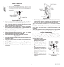
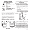
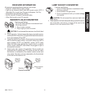
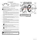
Swivel
Ball
Mount
Ball Mounting
Bracket
Ball Mounting
Bracket Screw
Tab
Rear of Sensor
Tab Slots
Attaching Ball Mounting Bracket to Indoor Motion Sensor
(Vertical Installation Shown)
Note: Mount the indoor motion sensor so that it can be angled up or
down to give you the desired coverage above the oor level.
1. Attach ball mounting bracket to rear of motion sensor. The ball
mounting bracket is designed to mount to the rear of the sensor
in three possible directions depending upon the installation
requirements. To attach the ball mounting bracket, follow the
steps shown below:
• Determine the best mounting position of the sensor for the
coverage desired.
• Determine the best location of the wall mounting bracket.
• Insert the tabs on the ball mounting bracket into the tab slots
on the rear of the sensor that best align the sensor with the
wall mounting bracket.
• Remove the batteries.
• Using a philips-head screwdriver, insert mounting screw into
the hole in the battery compartment that aligns with the hole
on the rear of the ball mounting bracket. Tighten securely.
2. Place sensor mounting bracket against surface to be mounted
on and mark hole locations with pencil or center punch.
3. Using a 2.5 mm (0.1”) drill bit, drill two pilot holes for mounting
screws. If not mounting directly to wood or wood stud, drill 5 mm
(0.2”) pilot holes and use the included wall anchors.
4. Attach indoor motion sensor mounting bracket to a sturdy object
(i.e. wall, ceiling, post, etc.) using two screws provided. Make sure
unit has an unobstructed view. Note: Attach mounting bracket
vertically if connecting to a curved surface such as a post.
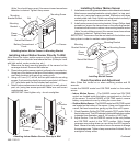
5. Install motion sensor to mounting bracket. Using a Philips-head
screwdriver, loosen the clamp screw on the mounting bracket.
Insert swivel ball mount on sensor into mounting bracket socket


