


Lamp 2
Lamp 1
11
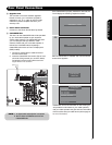
First time use
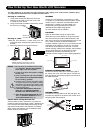
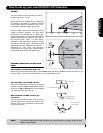
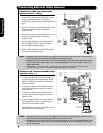
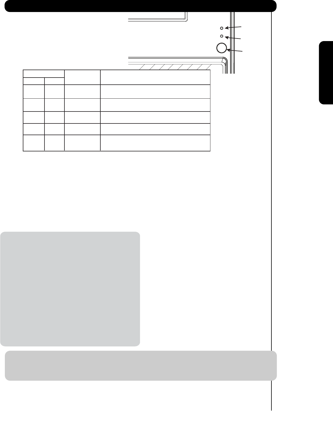
ቪ REMOTE CONTROL sensor
Point your remote at this area when selecting
channels, adjusting volume, etc.
ቪ IR OUT sensor
Point your equipment’s remote control at this area.
The IR will pass through the IR Blaster cables
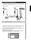
ቫ SIDE INPUT JACKS (for INPUT:5)
INPUT 5 provide Y-PBPR jacks for
connecting equipment with this capability, such as
a DVD player or Set Top Box. You may use
composite video signal for this input.
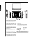
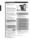
Front/Side Panel Controls
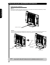
ቩ POWER light indicator
To turn the TV ON, press the main power
switch located on the lower right side of the
TV. A red stand-by indicator lamp located on
the lower right of the front bezel will
illuminate. The LCD TV is now ready for
remote ON/OFF operation.
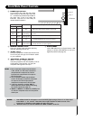
Indicating Lamp Power Status Operating
When the main power switch is set to O.
OFF.
When the main power switch on the TV
(Stand-by) is ON.
Blinking
Blue
nO
TV MAIN POWER is ON with no signal input
(Power Saving) except antenna
(no sync. signal).
Lamp 1 Lamp 2
Off
Off
Lights
Red
Off
OFF.
Lights
Blue
Off
Off
(Turning ON )
OFF.
TV MAIN POWER is ON ; but no picture is shown.
TV MAIN POWER is ON ; picture is shown.
Lights
Orange
Off
Off
NOTES: 1. Your HITACHI LCD TV will appear to be turned OFF (lights orange) if there is no video input
when INPUT : 1, 2, 3, 4 and 5. Check the Power Light condition to make sure the TV is
turned off or in Stand-by mode (lights red) when not in use.
2. Remote Control can not turn ON/OFF the “MAIN POWER” of the TV.
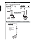
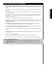
Your component outputs may be labeled
Y, B-Y, and R-Y. In this case, connect the
components B-Y output to the TV’s PB
input and the components R-Y output to
the TV’s P
R input.
Your component outputs may be labeled
Y-C
BCR. In this case, connect the component
C
B output to the TV’s PB input and the
component C
R output to the TV’s PR input.
It may be necessary to adjust TINT to
obtain optimum picture quality when using
the Y-P
BPR inputs (see page 43).
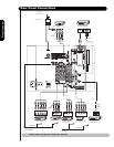
INPUT 3, INPUT 4 and INPUT 5 (Y/VIDEO) can
be used for composite video and component
video input.
NOTE: 1.
2.
3.
4.
ቭ
PHOTO INPUT
Insert USB cable from your Digital Camera, USB
memory or memory card USB drive to view your
digital still pictures (see page 27).
to your equipment.
IR Sensor