


CONNECTING A/V NETWORK
19
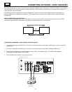
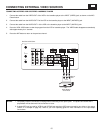
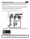
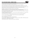
Your Hitachi Plasma Television is equiped with an A/V Network feature. This feature helps to control your external Audio/Video
equipment (VCR, Set Top Box, DVD, etc.). Once this is setup, it allows your IR Mouse connector to control your equipment using
your Hitachi Plasma TV Remote Control. You can use your Hitachi remote control to control the Audio/Video equipment command
without the equipment’s remote control.
The Plasma Television AVC Center has 2 IR BLASTER jacks. Each IR Mouse cable can connect up to 2 external Audio/Video
components. Therefore, you can connect the Plasma Television with up to four components. Please see the following example of
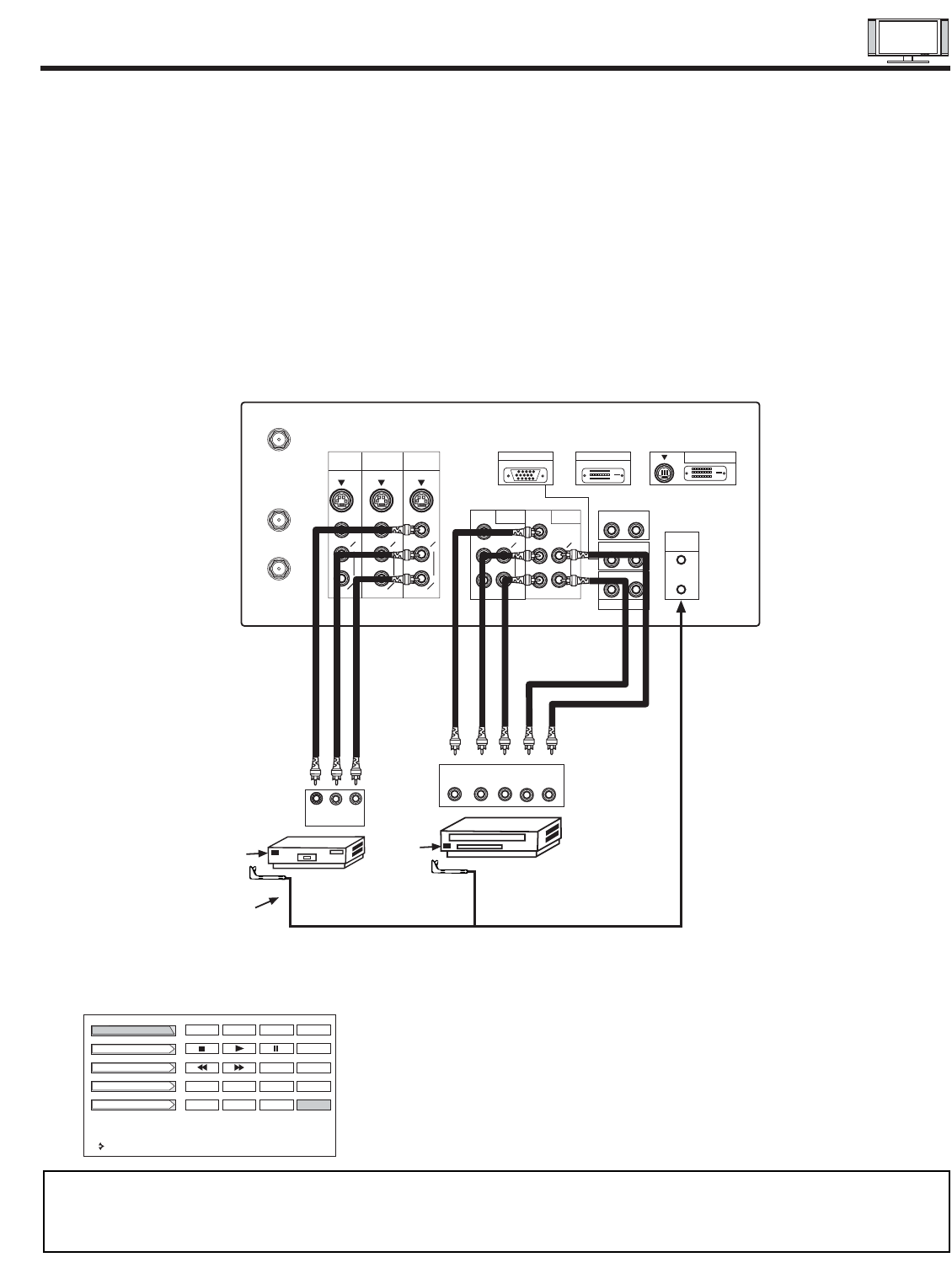
an A/V Network setup between your Hitachi Plasma Television and external Audio/Video equipment (VCR and DVD Player).
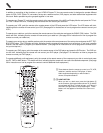
CONNECTING EXTERNAL AUDIO/VIDEO COMPONENTS TO IR BLASTER FOR A/V NETWORK
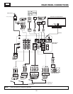
1. Connect your external Audio/Video components to the AVC Center shown on pages 13~18.
2. Connect the IR Mouse cable to the IR BLASTER output of the AVC Center.
3. Place the IR mouse in front of the infrared sensor of the external components you wish to control.
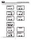
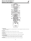
4. Press the A/V NET button on the remote control. Use THUMB STICK ̆ or ̄ to highlight the component you wish to set up.
Use THUMB STICK ̈ to enter component’s “SOFT KEY” control button. The A/V Network Setup Wizard will automatically
start upon the very first use. You can access the Setup Menu Wizard again in the future by pressing the A/V net button and
selecting SETUP.
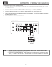
NOTES: 1. The AVC Center has two IR BLASTER outputs which can control up to a total of four external components.
2. The IR Mouse must be placed in front of the external components infrared sensor for the A/V Network to work.
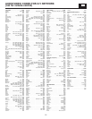
3. The correct codes must be entered for each of the Audio/Video components for the A/V Network to function properly.
4. Audio/Video component codes for A/V network are on page 21.
DVD Player
ANT A
TO
CONVERTER
ANT B
AUDIO
(MONO)
L
R
S-VIDEO
VIDEO
MONITOR
OUT
INPUT 4 INPUT 3
Y/VIDEO
AUDIO
L
R
(MONO)
INPUT 2
AUDIO
L
R
(MONO)
INPUT 1
AUDIO
AUDIO
AUDIO
AUDIO OUT
Y
IR
BLASTER
RGB 2
TO MONITOR
V L R
OUTPUT
VCR
Infrared
Sensor
Infrared
Sensor
IR
Mouse
OUTPUT
YP
B
/C
B
P
R
/C
R
R L
AUDIO
(MONO)
L
R
S-VIDEO
VIDEO
AUDIO
(MONO)
L
R
S-VIDEO
VIDEO
P
B
P
R
P
B
P
R
R L
R L
R L
ANALOG INPUT
RGB 1
DIGITAL INPUT
Rear Panel of the AVC Center
DVD
Amplifier
Cable Box
Set Top Box
VCR
Move
POWER
TV/VCR
CH
̄
CH
̆
SETUP
b
MORE