


14
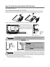
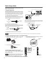
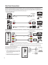
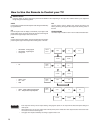
The SIDE panel VIDEO and S-VIDEO jacks are provided as a convenience to allow you to easily connect a Camcorder, DVD, Video
Game and a VCR as shown in the following examples. (When connecting an S-VIDEO device, also connect the audio output into the
Side Audio Input jacks).
Completely insert connection cord plugs when connecting to side panel jacks. If you do not, the played back picture may •
be abnormal.
Cable plugs are often color-coded. Match colors of plugs and terminals, i.e. connect red to red, white to white, etc.•
When making video connections, connect S-Video only or Video only. If both are connected, S-Video takes priority.•
•
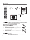
NOTES
For monaural devices, please connect Audio signal cable into L/Mono input jack .
or
IN OUT
o
r
[PC sample]
(Audio)
(D-sub 15 Pin)
RGB
RGB
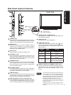
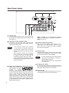
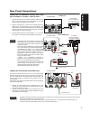
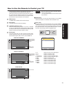
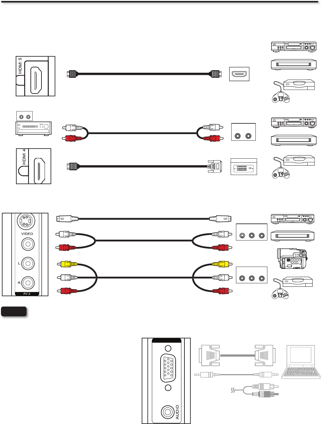
Connecting a Personal Computer PC .
Use the RGB PC connection terminal and the Analog
Audio Input terminals to connect the PC.
Connect the RGB 1.
(D-sub 15 Pin) and AUDIO
cable from the RGB and AUDIO OUT jack of the
PC to the RGB and AUDIO jack, as shown on the
Side Panel on the right.
Press the INPUT button, then select RGB from the 2.
INPUTS menu to view the signal from the PC.
OR
COMPOSITE VIDEO or
S-VIDEO OUTPUT CAPABILITY
R (Red)
L (White)
VIDEO (Yellow)
R (Red)
L (White)
VIDEO (Yellow)
OUTPUT
VIDEO
L R
SIDE INPUT PANEL
DVD player
VCR
Home video game system
Camcorder
L (White)
R (Red)
L (White)
R (Red)
OUTPUT
S-VIDEO
L R
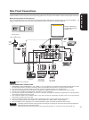
Side Panel Connections
The following connection diagrams are offered as suggestions. However, you may need to modify them to accommodate your particular
assortment of components and features. For best performance, video and audio cables should be made from coaxial shielded wire.
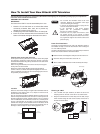
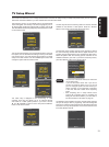
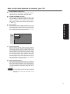
There are 2 SIDE panel HDMI jacks provided as a convenience to allow you to easily connect HDMI or DVI signals from a DVD,
Set-Top-Box, Video Game as shown in the following examples (When a DVI product is connected, the use of a separate audio device is
necessary for audio, use an Audio Amplifier and connect to the Audio In jacks).
A) Connecting HDMI signal
[HDMI] [HDMI]
SIDE INPUT PANEL
HDMI DIGITAL
OUTPUT CAPABILITY
HDMI OUT
DVD player
Set-Top Box
Home video game system
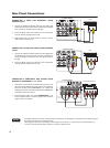
B) Connecting DVI signal
DIGITAL OUTPUT
OUTPUT
L R
DVI to HDMI Cable
[HDMI] [DVI]
R (Red)
L (White)
R (Red)
L (White)
DVI DIGITAL
OUTPUT CAPABILITY
SIDE INPUT PANEL
DVD player
Set-Top Box
Home video game system
Audio Amplifier
AUDIO IN
L R