


51-52-03-07
Page 2
Features, continued
CE
Mark-
Conformity with
73/23/EEC, Low Voltage Directive
and 89/336/EEC, the EMC Directive
Moisture Resistant Front Panel -
Capable of meeting NEMA 3 and
IEC529 IP65 (i.e. hosedown)
requirements.
Timer -
This standard feature pro-
vides a configurable time period of
0 to 99 hours, 59 minutes. Alarm 1
is dedicated to be active at the end
of the timeout period. Timer “start”
is selectable as either the
RUN/HOLD key or Alarm 2. The
optional Digital Input can also be
configured to start the Timer in
addition to either the keyboard or
Alarm 2. The Timer status shown in
the lower display is selectable as
either time remaining or elapsed
time.
Two Sets of Tuning Constants -
Two sets of PID parameters can be
configured for each loop and
automatically selected.
Heat/Cool Capability -
Provides
split range control with independent
PID tuning constants - one for
heating, one for cooling, plus mixed
output forms.
Alarm Selection -
None, one, or
two relays to activate external
equipment when preset high/low
setpoints are reached. There is an
indicator for each alarm.
Setpoint Ramp -
Provides single
programmable setpoint ramp of up
to 255 minutes duration which is
repeatable and activated by the
Run/Hold key.
Output Rate Limiter -
A maximum
output rate may be configured for
both the upscale and downscale
output directions.
Data Security -
Five levels of key-
board security protect tuning,
configuration, and calibration data,
accessed by a configurable 4-digit
code. Nonvolatile EEPROM
memory assures data integrity
during loss of power.
Quality/Support -
The UDC3000 is
covered by a 2-year warranty and
backed up by a toll-free phone
number for technical assistance.
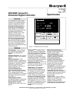
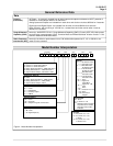
Optional Features (Fig. 4)
Second Input - Isolated high level
input available for remote setpoint
signal, PV signal via digital inputs,
or motor slidewire input. (Table 1)
Auxiliary Output* - This isolated
Auxiliary Output can be scaled from
4-20 mA for 0 to 100% for any
range. It can be configured to
represent Input 1, Input 2, PV,
active Setpoint, Local SP1,
Deviation, or the Control Output.
Communications* - Provides a link
between the UDC3000 and a
Honeywell supplied interface device
capable of communicating via
RS232 (DMCS), or direct
communication via the RS422/485
communications option to a host
computer.
Approval Body Options - FM
approval, CSA certification and UL
Recognition are available options.
UL Recognition applies to
regulatory use only.
2 Digital Inputs - Allows remote
dry contact closure to select one of
the following for each digital input:
• Manual control mode
• Local setpoint 1
• Local setpoint 2
• Direct controller action
• Reset of Limit Controller
• Hold SP Ramp/Programming
• Select PID set 2
• PV = Input 2
• External program reset
• Disable PID integral action
• To Run - SP Ramp/Program
• To Automatic output value
• Manual mode, failsafe output
• Disable keyboard
• Start Timer
• To Auto/Manual Station
• ToTune
Also allows the following selections
to be combined with the above
selections:
• Select PID set 2
• Direct controller action
• Local setpoint 2
• Disable adaptive tune
Transmitter Power - Provides up
to 30 volts to power a 2 wire
transmitter (requires use of alarm 2
open collector output selection or
auxiliary output.)
* AuxOut and communications are mutually
exclusive (only one may be specified).
Optional Features continued
Auto/Manual Station Plus Backup
Control - You can use a single
UDC3000 to act as both an
Auto/Manual Station PLUS a back-
up PID Controller, should the
primary loop controller fail. Since
the PID control is sometimes
implemented in the PLC, this
feature provides a very cost-
effective way to insure the process
does not have to shutdown or
remain in manual mode if the PLC
should fail. Switching from the
Auto/Manual Station to the back-up
control mode is accomplished using
the Digital Input option.
Setpoint Ramp/Soak
Programming - Enables you to
program and store 6 Ramp and 6
Soak segments for setpoint
programming. Run or Hold of
program is keyboard or remote
switch selectable.
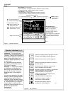
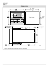
Physical Description
The controller is housed in a 5.8
inch deep, black metal case with a
dark gray elastomer bezel, that can
be panel mounted in a 1/4 DIN
cutout, (see Figure 5.) The plug-in
chassis allows easy access to the
controller board and its various
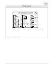
option boards. All power, input, and
output wiring are connected to
screw terminals on the rear panel,
(see Fig 6.) Blue and tan elastomer
bezels are optionally available.
Inputs
Each analog input is sampled 3
times a second, amplified and
then converted to a digital signal
which is isolated and passed to
the microprocessor. The primary
input can be one of various
Thermocouple, Radiamatic, or
Linear actuations, (see Table 1.)
A second input provides a remote
setpoint function and accepts a 4
to 20 mA or 1 to 5 Vdc range that
can be characterized. All ranges
are keyboard selectable. External
cold junction compensation is
provided. You can select upscale
downscale, or failsafe sensor
break protection. A configurable
digital filter of 0 to 120 seconds for
each Input provides input signal
smoothing, if required.