


51-52-03-07
Page 4
ALM
RSP
OUT
%
1 2
1 2
1 2
F C
MAN
FUNCTION
SET UP
LOWER
DISPLAY
MANUAL
AUTO
SETPOINT
SELECT
RUN
HOLD
DI
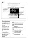
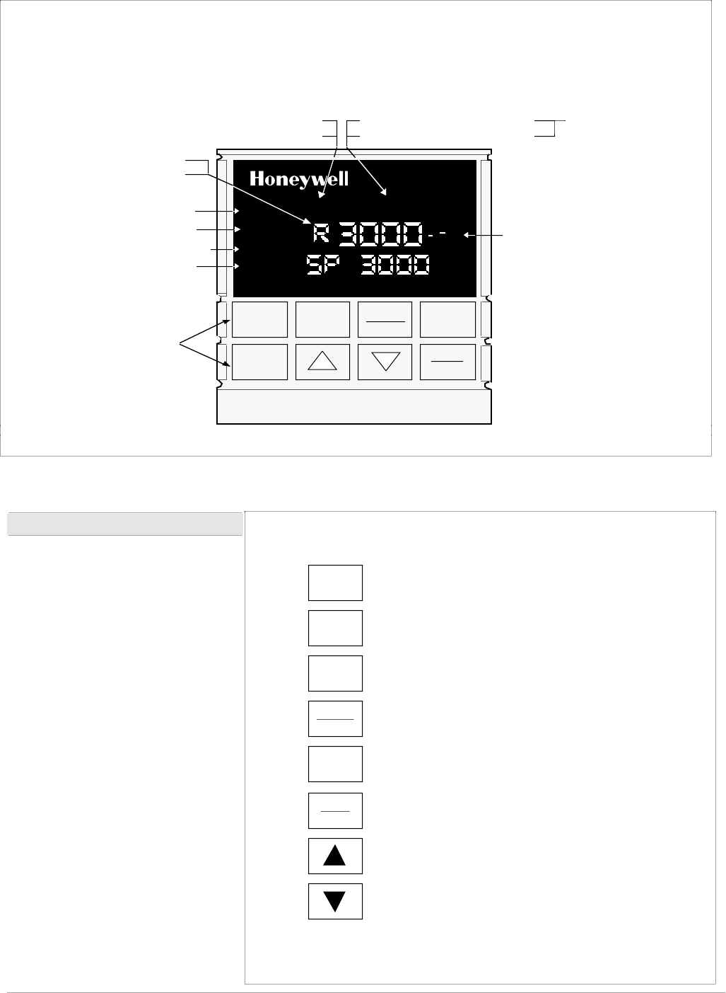
Indicator definition when lit
ALM - Alarm conditions exist
DI - Digital Input active
OUT - Control Relay 1 or 2 on
Upper Display - Six Characters
• Normal Operation - four digits dedicated to display the process variable
• Configuration Mode - displays parameter value or selection
Lower Display - eight characters
• Normal Operation - displays operating parameters and values
• Configuration Mode - displays function groups and parameters
MAN - controller in manual mode
A - controller in automatic mode
F - °Fahrenheit being used
C - °Centigrade being used
Indicator definition when lit
Deviation Bargraph
• Center bar indicates PV is
within ± 1% of setpoint.
• Next bar will light if PV is
between ±1% but less than
±2% in deviation.
• If PV is equal to or greater than
±10% deviation, the center bar
plus all ten deviation bars will
light.
MAN and A off —
communications
option active
Keys - See below
R - Run SP Ramp/Program
H - Hold SP Ramp/Program
RSP - Remote SP or SP2 active
22816
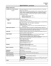
Figure 2 - Operator Interface
Operator Interface (Fig. 2)
Indicators - They provide alarm,
control mode, and temperature units
indication. There is also indication of
when Remote Setpoint is active, the
status of the control relays, and
whether a setpoint program is in Run
or Hold mode.
A 21-segment bargraph displays
deviation to ±10% of span and an
“On-Control” indicator.
Displays - A 4-digit upper display
is dedicated to the process vari-
able during normal operation with
alternate 6-character information
displayed when in the configure
mode.
During normal operation, the lower
display shows key-selected operat-
ing parameters such as Output,
Setpoints, Inputs, Deviation, active
Tuning Parameter Set, Timer Status,
or minutes remaining in a setpoint
ramp (4 digits). It also provides
guidance, through prompts, for the
operator during controller
configuration
(8-characters).
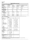
Selects Manual or Automatic control mode.
(may be disabled via configuration)
FUNCTION
Selects functions within each Set Up group.
LOWER
DISPLAY
Selects an operating parameter to be shown in
the lower display.
SET UP
Sequentially displays Set Up groups and allows
Function key to display individual functions.
SETPOINT
SELECT
RUN
HOLD
Initiates or holds the single setpoint ramp
or Ramp/Soak program.
(may be disabled via configuration)
Decreases the setpoint, output, or
configuration values displayed.
Alternately selects Local setpoint 1 and Remote
setpoint or between two local setpoints.
(may be disabled via configuration)
22071
MANUAL
Increases the setpoint, output, or
configuration values displayed.
AUTO
Figure 3 - Key Functions