


51-52-03-07
Page 7
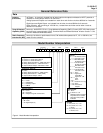
Specifications (continued)
Design (continued)
Auxiliary Linear Output (Optional)
(Isolated)
21 mA dc maximum into a negative or positive grounded load or non-grounded
load of 0 to 1000 ohms.
Output range can be set anywhere between 0 to 21 mA, and as direct or reverse
action. It can be configured to represent either Input, PV, Setpoint, Deviation, or
Control output. The range of the auxiliary output, as a function of the selected
variable, can be scaled. This output can be used as a second current output for
current duplex outputs.
Resolution:
12 bits over 0 to 21 mA
Accuracy:
0.2% of full scale
Temperature Stability:
0.01% F.S. / ˚C
Communications Interface (Optional)
DMCS
Baud Rate:
19200 baud
Length of Link:
4000 ft maximum
Link Characteristics:
Two wire, multi-drop proprietary protocol, 31 drops maximum
RS422/485
Baud Rate:
300, 600, 1200, 2400, 4800, or 19,200 baud
Parity:
Odd or Even
Length of Link:
4000 ft maximum
Link Characteristics:
Two wire or four wire, multi-drop RS422 ASCII protocol, 15
drops maximum
Digital Inputs (Optional) +15 Vdc source for external dry contacts or isolated solid state contacts. The
Digital Input option detects the state of external contacts for either of the two inputs.
On contact closure the controller will respond according to how each digital input is
configured. Opening contact causes return to previous state.
Input Filter
Software
: Single pole lowpass section with selectable time constants, off to 120
seconds available on both analog inputs.
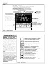
Digital Displays Vacuum fluorescent, alphanumeric.
A six-character upper display dedicated to the process variable (4 digits).
Alternate information displayed during configuration mode.
A eight-character lower display primarily shows key selected operating parameters
(4 digits). Also provides guidance during controller configuration.
Indicators Alarm Relay Status (ALM 1 or 2)
Control Mode (A or MAN)
Temperature Units (F or C)
Remote Set Point or SP2 Active (RSP)
Control Relay Status (OUT 1 or 2)
Digital Input Status (DI 1 and 2)
Bargraph 21 segment, vertical Deviation bargraph
Center bar lit when “on” control
Deviation to ± 10% of PV span in 1% increments
Modes of Operation Manual
Automatic with local setpoint
Automatic with remote setpoint (2-input units only)
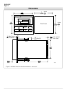
Dimensions See Figure 5.
Mounting Panel-mounted, 5.82 inch depth
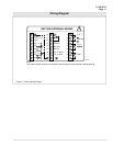
Wiring Connections Screw terminals on the rear of the case. (See Figure 6.)
Power Consumption 18 VA maximum
Power Inrush Current
10A Max. for 4 ms (under operating conditions)
CAUTION
When applying power to more than one UDC3000, make sure that
sufficient power is supplied. Otherwise, the controllers may not start up normally
due to voltage drop from the inrush current.
Weight 1.3 kg (3 lbs.)