Overview and Controls
10
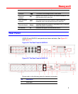
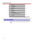
2 Audio input
3 Video CVBS output
4 Audio output
5 Network port
6 USB port
7 HDMI port
8 RS232 port
9 Video VGA output
10 Alarm input/alarm output/RS485 port
11 12VDC Power input port
12 Power button
When connecting the Ethernet port, please use a straight cable to connect
the PC and use the crossover cable to connect to the switcher or router.
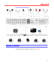
Connection Diagram
Please refer to Figure 2-4 for connection diagram of HSVR-16. HSVR-04’s
is similar.


