


R7140G,L,M BURNER CONTROL MODULES
66-1153—03 26
STATIC CHECKOUT
After checking all wiring, perform this checkout before
installing the R7140 on the subbase. These tests verify the
Q520A Wiring Subbase is wired correctly, and the external
controllers, limits, interlocks, actuators, valves, transformers,
motors and other devices are operating properly.
WARNING
Explosion and Electrical Shock Hazard.
Can cause serious injury, death, or equipment
damage.
1. Close all manual fuel shutoff valve(s) before starting
these tests.
2. Use extreme care while testing the system. Line
voltage is present on most terminal connections
when power is on.
3. Open the master switch before installing or
removing a jumper on the subbase.
4. Before continuing to the next test, be sure to
remove test jumper(s) used in the previous test.
5.
Replace all limits and interlocks that are not operating
properly. Do not bypass limits and interlocks.
CAUTION
Equipment Damage Hazard.
Improper testing can damage equipment.
Internal surge protectors can break down and conduct
a current, causing the R7140 to fail the dielectric test
or possibly destroy the internal lightning and high
current protection. Do not perform a dielectric test with
the R7140 installed.
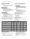
Equipment Recommended
1. Voltmeter (1M ohm/volt minimum sensitivity) set on the
0-300 Vac scale.
2.
Two jumper wires; no. 14 wire, insulated, 12 inches
(304.8 mm) long with insulated alligator clips at both ends.
3. When jumpered to Ignition, Pilot and Main Valves, use
ammeter in series and verify proper current draw.
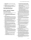
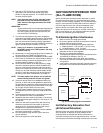
General Instructions
1. Perform all applicable tests listed in Static Checkout,
Table 8, in the order listed.
2. Make sure all manual fuel shutoff valve(s) are closed.
3. Perform only those tests designated for the specific
R7140 model being tested.
4. Raise the setpoint of the operating controller to simulate
a call for heat.
5. For each test, open the master switch and install the
jumper wire(s) between the subbase wiring terminals
listed in the Test Jumpers column.
6. Close the master switch before observing operation.
7. Read the voltage between the subbase wiring terminals
listed in the Voltmeter column.
8. If there is no voltage or the operation is abnormal, check
the circuits and external devices as described in the last
column.
9. Check all wiring for correct connections, tight terminal
screws, correct wire, and proper wiring techniques.
Replace all damaged or incorrectly sized wires.
10. Replace faulty controllers, limits, interlocks, actuators,
valves, transformers, motors and other devices as
required.
11. Make sure normal operation is obtained for each
required test before continuing the checkout.
12. After completing each test, be sure to remove the test
jumper(s).
WARNING
Explosion Hazard.
Can cause serious injury or death.
Make sure all manual fuel shutoff valves are closed
before performing static checkout.
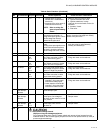
Table 8. Static Checkout.
Test
No. R7140 Models
Test
Jumpers Voltmeter Normal Operation
If Operation is Abnormal,
Check the Items Listed Below
1 All None L1-L2 Line voltage at terminal L1. 1. Master Switch.
2. Power connected to the Master Switch.
3. Overload protection (fuse, circuit breaker,
etc.) has not opened the power line.
2 16-L2 Line voltage at terminal 16 (4 on
Pre-Ignition Interlock devices).
1. Limits.
2. Burner Controller.
3 4-L2 Line voltage at terminal 16. 1. Pre-Ignition interlocks.
4 L1-8 3-L2 1. Burner motor (fan or
blower) starts.
2. Line voltage at terminal 3
within 10 seconds.
1. Burner motor circuit.
a. Manual switch of burner motor.
b. Burner motor power supply, overload
protection, and starter.
c. Burner motor.
2. Running or Lockout Interlocks (including
Airflow Switch).
5 L1-18 — Ignition spark (if ignition
transformer is connected to
terminal 18).
1. Watch for spark or listen for buzz.
a. Ignition electrodes are clean.
b. Ignition transformer is okay.