


R7140G,L,M BURNER CONTROL MODULES
66-1153—03 30
20. Run the burner through another sequence, observing
the flame signal for:
a. Pilot flame alone.
b. Pilot and main flame together.
c. Main flame alone (unless monitoring an intermittent
pilot). Also observe the time it takes to light the main
flame. Ignition of main flame should be smooth.
21. Make sure all readings are in the required ranges before
proceeding.
22. Return the system to normal operation.
NOTE: After completing these tests, open the master
switch and remove all test jumpers from the
subbase terminals, limits/controls or switches.
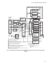
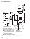
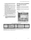
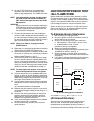
Direct Spark Ignition Systems
This check applies to gas and oil burners not using a pilot. It
should immediately follow the preliminary inspection. Refer to
the appropriate sample block diagram of field wiring for the
ignition transformer and fuel valve(s) hookup.
NOTE:Low fuel pressure limits, if used, could be open. If so,
bypass them with jumpers during this check.
1. Open the master switch.
2. Complete the normal ready-to-fire checkout of the fuel
supply and equipment as recommended by the
equipment manufacturer.
3. Close all manual main fuel shutoff valve(s). Check that
the automatic fuel valve(s) is closed. Make sure fuel is
not entering the combustion chamber.
4. Close the master switch and start the system with a call
for heat by raising the setpoint of the operating
controller; see the relay module sequencing. The
program sequence should start the INITIATE sequence.
5. Let the sequence advance through PREPURGE (if
applicable). Ignition spark should occur when the PILOT
LED turns on. Listen for the click of the first stage fuel
solenoid valve(s). The relay module locks out and the
ALARM LED turns on.
6. Let the R7140 Relay Module complete its cycle.
7. Open the manual fuel shutoff valve(s).
8. Push the reset button and the relay module recycles the
program sequence through PREPURGE (if applicable).
9. When the PILOT LED turns on, make sure that the first
stage burner flame is established. If it is, go to step 15.
10. If the first stage burner flame is not established within
four seconds, or within the normal lightoff time specified
by the equipment manufacturer, close the manual fuel
shutoff valve(s), and open the master switch.
11. Check all burner adjustments.
12. Wait about three minutes. Close the master switch,
open the manual fuel shutoff valve(s), and try to light off
the burner again. The first attempt may be required to
purge the lines and bring sufficient fuel to the burner.
13. If the first stage burner flame is not established within
four seconds, or within the normal lightoff time specified
by the equipment manufacturer, close the manual fuel
shutoff valve(s), and open the master switch.
14. If necessary, repeat steps 11 through 13 to establish the
first stage burner flame. Then go to step 15.
15. When the first stage burner flame is established, the
sequence advances to RUN. Make burner adjustments
for flame stability and input rating. If a second stage is
used, go to step 18.
16. Shut down the system by opening the burner switch or
by lowering the setpoint of the operating controller.
Make sure the burner flame goes out and all automatic
fuel valves close.
17. If used, remove the bypass jumpers from the low fuel
pressure limit and subbase.
18. If a second stage is used, make sure the automatic
second stage fuel valve(s) opened. Check the lightoff as
follows (or go to step 19):
a. Open the manual second stage fuel valve(s).
b. Restart the system by raising the setpoint of the
operating controller.
c. When the first stage burner flame is established, watch
for the automatic second stage fuel valve(s) to open.
Observe that the second stage lights off properly.
d. Make burner adjustments for flame stability and
input rating.
e. Shut down the system by lowering the setpoint of
the operating controller. Make sure the burner flame
goes out and all automatic fuel valves close.
f. Go to step 19.
19. Restart the system by closing the burner switch and/or
raising the setpoint of the operating controller. Observe
that the burner flame is established during PILOT IGN,
within the normal lightoff time specified by the
equipment manufacturer.
20.
Measure the flame signal. Continue to check for the proper
signal through the RUN period. Check the signal at both
high and low firing rate positions and while modulating. Any
pulsating or unsteady readings require further attention.
21. Make sure all readings are in the required ranges before
proceeding.
NOTE: On completing these tests, open the master
switch and remove all test jumpers from the
subbase terminals, limits/controls or switches.
22. Return the system to normal operation.
PILOT TURNDOWN TEST (ALL
INSTALLATIONS USING A
PILOT)
Perform this check on all installations that use a pilot. The
purpose of this test is to verify that the main burner can be lit
by the smallest pilot flame that can hold in the flame amplifier
and energize the FLAME LED. Clean the flame detector(s) to
make sure that it detects the smallest acceptable pilot flame. If
using AMPLI-CHECK™ or self-checking amplifier and 1M
ohm/volt meter, the flame signal fluctuates every time the
amplifier does a self-check or a shutter check.
NOTE: Low fuel pressure limits, if used, could be open.
If so, bypass them with jumpers during this test.
1. Open the master switch.
2. Close the manual main fuel shutoff valve(s).
3. Connect a manometer (or pressure gauge) to measure
pilot gas pressure during the turndown test.
4. Open the manual pilot shutoff valve(s).
5. Close the master switch and start the system with a call
for heat. Raise the setpoint of the operating controller.
The 7800 Series sequence should start, and PRE-
PURGE (if applicable) should begin.