


R7140G,L,M BURNER CONTROL MODULES
66-1153—03 28
SYSTEM CHECKOUT
IMPORTANT
Perform all Static Checkout Procedures for the
applicable relay module shown in Table 8 before
starting these procedures.
WARNING
Explosion Hazard.
Can cause serious injury or death.
Do not allow fuel to accumulate in the combustion
chamber for longer than a few seconds without igniting
to prevent danger of forming explosive mixture.
Close manual fuel shutoff valve(s) if flame is not
burning at end of specified time.
WARNING
Electric Shock Hazard.
Can cause serious injury or death.
1. Use extreme care while testing system. Line voltage
is present on most terminal connections when
power is on.
2. Open master switch before removing or installing
R7140 Relay Module.
Make sure all manual fuel shutoff valve(s) are closed before
starting initial lightoff check and Pilot Turndown tests.
Do not put the system in service until you have satisfactorily
completed all applicable tests in this section and any others
recommended by the original equipment manufacturer.
Limit trial for pilot to ten seconds. Limit the attempt to light
main burner to two seconds after fuel reaches burner nozzle.
Do not exceed manufacturer nominal lightoff time.
CAUTION
Equipment Malfunction or Damage Hazard.
Incorrect wiring can cause equipment damage.
Each relay module type is unique. Using existing
wiring on a relay module change can cause equipment
damage.
IMPORTANT
1. If the system fails to perform properly, refer to the
Troubleshooting section.
2. Repeat all required Checkout tests after all
adjustments are made. All tests must be satisfied
with the flame detector(s) in their final position.
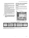
Equipment Recommended
S7800A Keyboard Display Module
Volt-ohmmeter (1M ohm/volt minimum sensitivity) with:
• 0-300 Vac capability.
• 0-6000 ohm capability.
• 0-10 Vdc capability.
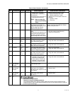
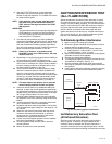
Checkout Summary
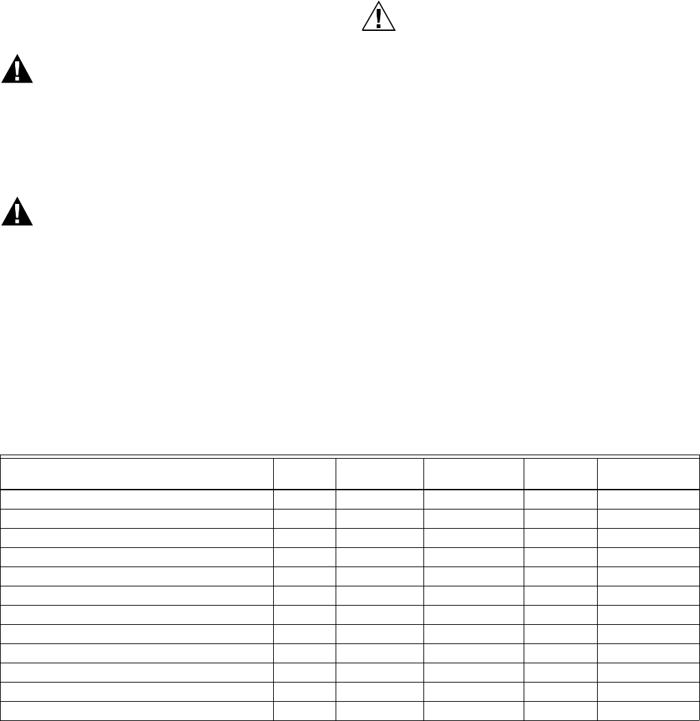
Table 9 provides an overview of checkout steps performed for
each applicable system.
See Installation Instructions for location of component parts
and terminal locations.
Table 9. Checkout Steps and Applicable Detection Systems.
Preliminary Inspection
Perform the following inspections to avoid common problems.
Make certain that:
1. Wiring connections are correct and all terminal screws
are tight.
2. Flame detector(s) is clean, installed and positioned
properly. Consult the applicable Instructions.
3. Combination of amplifier and flame detector(s) is
correctly used. See the amplifier specifications.
4. Plug-in amplifier and purge card (if required) are
securely in place.
5. Burner is completely installed and ready to fire; consult
equipment manufacturer instructions. Fuel lines are
purged of air.
6. Combustion chamber and flues are clear of fuel and fuel
vapor.
Checkout Step
Piloted
Systems DSI Systems
Infrared Flame
Detectors
Flame Rod
Systems
Ultraviolet
Flame Detectors
Preliminary Inspection X X X X X
Flame Signal Measurement X X X X X
Initial Lightoff Check for Proved Pilot X
Initial Lightoff Check for Direct Spark Ignition X
Pilot Turndown Test X
Ignition Interference Test X
Hot Refractory Saturation Test X
Hot Refractory Hold-in Test X X X X X
Ignition Spark Pickup X
Response to Other Ultraviolet Sources X
Flame Signal with Hot Combustion Chamber X X X X X
Safety Shutdown Tests X X X X X