


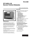
R7140G,L,M BURNER CONTROL MODULES
66-1153—03 8
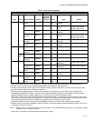
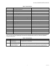
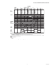
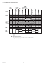
* Check terminal 8 and 15.
If jumpered, ST7800A1031 (7 second purge).
If not jumpered, ST7800A1039 (30 second purge).
Mounting R7140 Relay Module
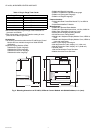
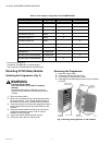
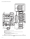
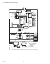
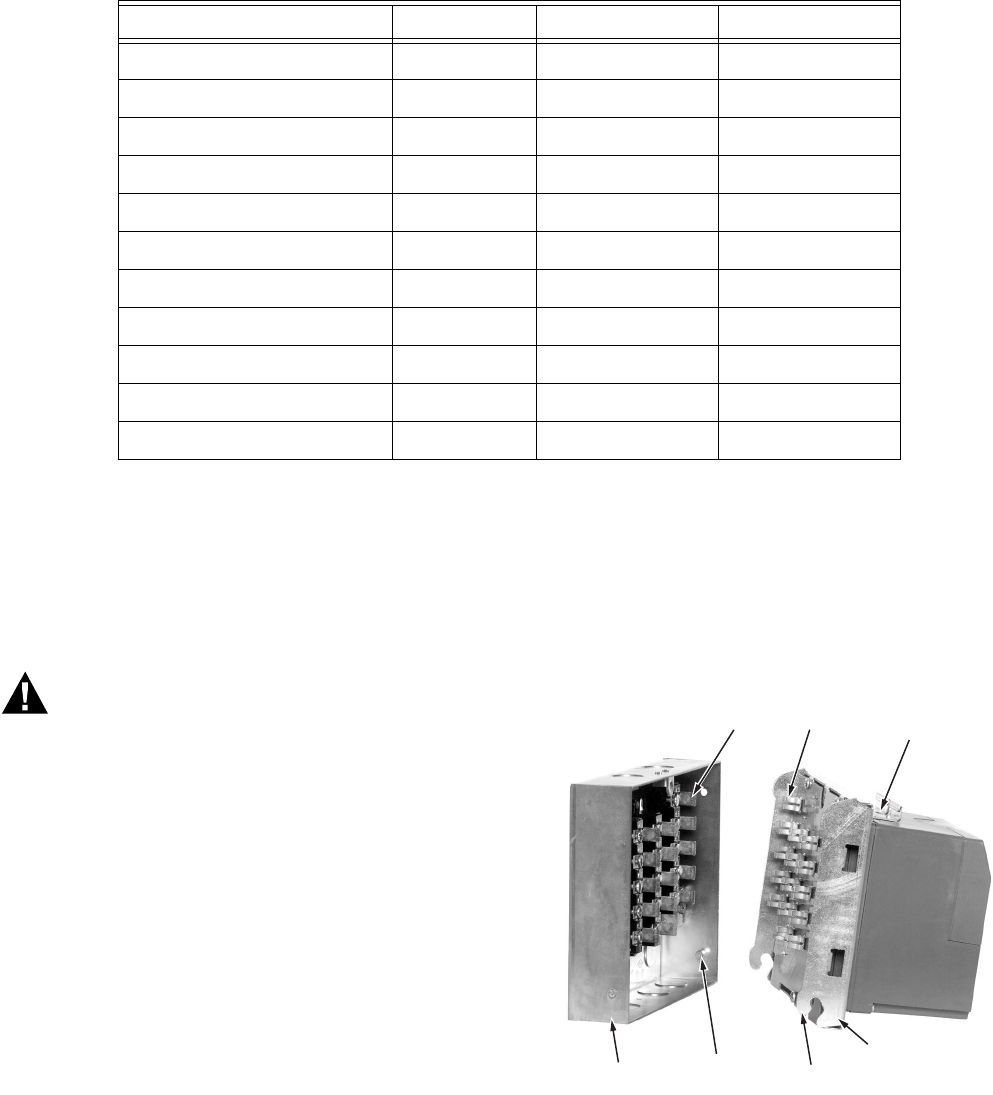
Installing the Programmer (Fig. 3)
WARNING
Electrical Shock Hazard.
Can cause severe injury, death or property
damage.
Disconnect power before installation to prevent
electrical shock. More than one disconnect may be
involved.
1. Open the master switch.
2. Make sure no subbase wiring is projecting out beyond
the terminal blocks. Tuck in wiring against the back of
the subbase so it does not interfere with the contacts.
3. Grasp the programmer chassis and engage the chassis
hinge brackets with the pivot pins at the bottom of the
subbase.
4. Swing the chassis inward until the spring connectors
engage the knifeblade contacts. Push in until the
contacts are fully engaged.
5. Tighten the chassis retaining screw securely.
6. Close the master switch to restore power.
Removing the Programmer
1. Open the master switch.
2. Loosen the chassis retaining screw.
3. Pull outward on the top of the chassis.
4. Disengage the chassis hinge brackets from the subbase
pivot pins.
Fig. 3. Mounting the programmer on the subbase.
Table 6. J1/J2 Jumper Configuration for R4140M/PM720M.
Model Purge Timer Leave J1 & J2 Remove J1 and J2
R4140M1004/M1012 A1039 X
R4140M1020/M1038 A1047 X
R4140M1046/M1053 A1062 X
R4140M1079 (GP101) A1062 X
R4140M1103/M1111 A1039 X
R4140M1145/M1152 A1047 X
R4140M1160/M1178 A1062 X
R4140M1186 A1047 X
R4140M1194 ST7800A1062
BC7000L1000 w/PM720M2002 ST7800A1062 X
BC7000L1000 w/PM720M2036 * X
CHASSIS
RETAINING
SCREW
SPRING
CONNECTORS
KNIFE-BLADE
CONTACTS (20)
WIRING
SUBBASE
PIVOT PIN (2)
HINGE
BRACKET (2)
PROGRAMMER
CHASSIS
M22605