


R7140G,L,M BURNER CONTROL MODULES
27 66-1153—03
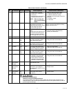
6 All L1-5 — 1. Ignition spark (if ignition
transformer is connected to
terminal 5).
2. Automatic pilot valve opens (if
connected to terminal 5).
NOTE: Refer to wiring dia-
gram of system being
tested.
1. Watch for spark or listen for buzz.
a. Ignition electrodes are clean.
b. Ignition transformer is okay.
2. Listen for click or feel head of valve for
activation.
a. Actuator, if used.
b. Pilot valve.
7 L1-6 — Same as test no. 6 for
connections to terminal 5. If
using direct spark ignition, check
the first stage fuel valve(s)
instead of the pilot valve.
Same as test no. 6. If using direct spark
ignition, check the first stage fuel valve(s)
instead of the pilot valve.
8 L1-7 — Automatic main fuel valve(s)
open.
If using direct spark ignition on a
model with intermittent pilot on
terminal 6, check the optional
second stage fuel valve, if used.
1. Listen for and observe operation of the
main fuel valve(s) and actuator(s).
2. Valve(s) and actuator(s).
9 L1-9 — Alarm (if used) turns on. 1. Alarm.
10 R7140G,L L1-8
and
10-11
13-L2 Firing rate motor drives open;
zero volts at terminal 13 after
motor starts driving open.
1. Low Fire Start Switch.
2. Firing rate motor and transformer.
11 R7140G,L L1-8
and
14-11
13-L2 Firing rate motor drives closed;
line voltage at terminal 13 after
motor is in Low Fire position.
1. Low Fire Start Switch.
2. Firing rate motor and transformer.
12 R7140G,L L1-8
and
10-11
15-L2 Firing rate motor drives open;
line voltage at terminal 15 after
motor is in High Fire position.
1. High Fire Purge Switch.
2. Firing rate motor and transformer.
13 R7140L L1-8
and
14-11
15-L2 Firing rate motor drives closed;
zero volts at terminal 15 after
motor starts driving closed.
1. Low Fire Start Switch.
2. Firing rate motor and transformer.
14 R7140G,L 11-12 — 1. Raise setpoint of Series 90
controller—firing rate motor
should drive toward open.
2. Lower setpoint of Series 90
controller—firing rate motor
should drive toward closed.
1. Series 90 Controller.
2. Firing rate motor and transformer.
15 R7140M with
open damper
contacts.
14-11 — If damper motor is used, motor
drives damper open.
Damper motor.
16 R7140M with
open damper
contacts.
L1-8 13-L2 If damper motor is used, motor
drives open; line voltage at
terminal 13 after motor is in Low
Fire position.
1. Low Fire Start Switch.
2. Damper motor.
17 R7140M with
open damper
contacts.
L1-8
and
L1-11
13-L2 If damper motor is used, motor
drives open; zero volts at
terminal 13.
1. Low Fire Start Switch.
2. Damper motor.
Final All
CAUTION
Equipment Damage Hazard.
Improper wiring can damage equipment.
On completing these tests, open the master switch and remove all test jumpers from the
subbase terminal. Also remove bypass jumpers from the low fuel pressure limits (if used) to
prevent equipment damage.
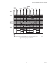
Table 8. Static Checkout. (Continued)
Test
No. R7140 Models
Test
Jumpers Voltmeter Normal Operation
If Operation is Abnormal,
Check the Items Listed Below