51-52-03-27
Page 11
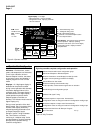
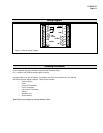
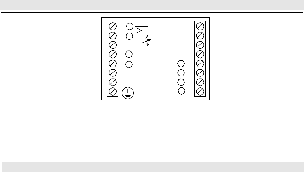
Wiring Diagram
8
7
6
5
4
L2/N
L1
IN1
CTL1
4-20mA
90-264V~
AL M2
CTL2
AL M1
OP TIO N
IN2
9
10
11
12
13
14
15
16
+
-
+
+
+
-
-
-
}
{
{
{
{
R
248 65
Figure 6—External Wiring Diagram
Ordering Information
For the complete ordering information, request Model Selection Guide
51-51-16-59 for UDC 2300 Universal Digital Controller.
Honeywell offers a full line of Sensors, Transmitters, and Final Control Devices for use with the
UDC 2300 Universal Digital Controller. These devices include:
• Thermocouples,
•RTDs,
• Pressure Transmitters,
• Flow Transmitters,
• Liquid Level Transmitters,
• Valves,
• Actuators, and
• Electric Motors.
Specifications are subject to change
without notice.


