


51-52-03-27
Page 2
Features/Options, continued
Auxiliary Output* (Optional)
—This
isolated Auxiliary Output can be
scaled from 4-20 mA for 0 to 100%
for any range. It can be configured to
represent Input 1, Input 2, PV, active
Setpoint, Local SP1, Deviation, or
the Control Output..
Communications* (Optional)
—
Provides a communications link
between the UDC 2300 and host
computer or PLC via the RS422/485
ASCII or Modbus® RTU
communications option.
Digital Input* (Optional)
—Provides
isolated digital input for remote dry
contact closure to select one of the
following actions:
• Manual control mode
• Local setpoint 1
• Local setpoint 2
• Direct controller action
• Hold SP Ramp/Programming
• Select PID set 2
• To Run - SP Ramp/Program
• External program reset
• Disable PID integral action
• Manual mode, failsafe output
• Disable keyboard
• Start Timer
• Initiate Tuning
• Initiate PV Hot Start
• Output tracks Input 2
• To Remote Setpoint
• To Latching Manual Mode
Also the digital input can allow
one of the following selections to
be combined with one of the
above selections:
• Select PID set 2
• Direct controller action
• Local setpoint 2
• Local setpoint 1
• To Run
New Alarm Function Features
• Alarms can be configured as
latching or non-latching.
• Alarm blocking is also available
which allows start-up without alarm
energized until after it first reaches
the operating region.
• PV rate of change alarm
• Loop break alarm
• Timer output reset
Universal Switching Power
—
Operates on any line voltage from 90
to 264 Vac 50/60 Hz without
jumpers. 24 Vac/dc instrument power
is available as an option.
*Auxiliary Output, Digital Input, and
Communications are mutually exclusive.
Features/Options, continued
Moisture Protection
—IP65/NEMA 3
rated front face permits use in
applications where it may be
subjected to moisture, dust, or hose-
down conditions.
Limit Control
—Provides a latching
relay , which is activated whenever
the PV goes above or below a preset
setpoint value. An alarm indicator will
light when the output is activated.
Reset is through a key on the front of
the controller or an external switch. A
FM approved model is available.
Approval Body Options
—FM
approval and CSA certification are
available options. A UL listing applies
to regulatory use only and is a
standard feature.
Timer
—This standard feature
provides a configurable time period of
0 to 99 hours, 59 minutes or units of
minutes and seconds. It can be
started via the keyboard, alarm 2, or
by a digital input. The timer output is
Alarm 1 which energizes at the end of
the Timer Period. Alarm 1 can be
automatically reset. The Timer Period
can be changed between each batch.
Status is shown on the lower display.
Heat/Cool Capability
—Provides split
range control with independent PID
tuning constants—one for heating,
one for cooling—plus mixed output
forms.
Setpoint Ramp/Soak Programming
(Optional)
—Enables you to program
and store six Ramp and six Soak
segments for setpoint programming.
Run or Hold of program is keyboard or
remote digital switch selectable.
Setpoint Rate
—Lets you define a
ramp rate to be applied to any local
setpoint change. A separate upscale
or downscale rate is configurable. A
single setpoint ramp is also available
as an alternative.
Thermocouple Failsafe
—
Configurable upscale or downscale
burnout and failsafe output level.
Decimal Point Location
—
Configurable for none, one, or two
places.
Indicator Model
—A single display
indicator model is available. Optional
features include: 2 alarms plus
Auxiliary Output or Communications.
Features/Options, continued
Dedicated Keys
—Provide direct
access setpoint modes and setpoint
program status to simplify and speed
operation.
Two Sets of Tuning Constants
—
Two sets of PID parameters can be
configured for each loop and
automatically or keyboard selected.
Alarm Selection
—None, one, or two
relays to activate external equipment
when preset high/low setpoints are
reached. There is an indicator for
each alarm. For Duplex or 3 Position
Step operation, only one alarm is
available.
Data Security
—Five levels of key-
board security protect tuning,
configuration, and calibration data,
accessed by a configurable 4-digit
code. Nonvolatile EEPROM memory
assures data integrity during loss of
power.
Diagnostic/Failsafe Outputs -
Continuous diagnostic routines detect
failure modes, trigger a failsafe output
value and identify the failure to
minimize troubleshooting time.
High Noise Immunity -
The
controller is designed to provide
reliable, error- free performance in
industrial environments that often
affect highly noise-sensitive digital
equipment.
Quality/Support
—The UDC 2300 is
covered by a 2-year warranty and
backed up by a toll-free phone
number for technical assistance.
Transmitter Power
—Provides up to
30 volts dc to power a 2-wire
transmitter. (Requires use of alarm 2
open collector output selection or
auxiliary output.).
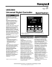
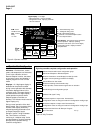
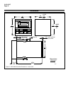
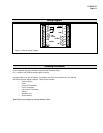
Physical Description
The controller is housed in a 4.2-inch
deep, black metal case with a dark
gray elastomer bezel, that can be
panel mounted in a 1/4 DIN cutout.
(See Figure 5.) The plug-in chassis
allows easy access to the controller
board and its various option boards.
All power, input, and output wiring are
connected to screw terminals on the
rear panel. (See Figure 6.) Blue and
tan elastomer bezels are optionally
available.