


51-52-03-27
Page 9
General Reference Data
Isolation
(Functional)
Analog Inputs :
are isolated from all other circuits at 850Vdc for 2 seconds, but not from each other.
Analog Outputs :
are isolated from all other circuits at 850Vdc for 2 seconds.
AC Power :
is electrically isolated from all other inputs and outputs to withstand a HIPOT potential of
1900Vdc for 2 seconds per Annex K of EN61010-1.
Relay Contacts :
with a working voltage of 115/230 Vac, are isolated from each other and all other
circuits at 345Vdc for 2 seconds.
Surge Withstand
Capability (SWC)
Immunity:
ANSI/IEEE C37.90.1, Surge Withstand Capability (SWC) (Formerly IEEE 472). Mains power
input and relay contact outputs: 2.5 kV, Common Mode and Differential Mode. All other circuits: 1.0 kV,
Common Mode and Differential Mode. The instrument is capable of meeting these test levels with no
component failures, no reset, and no incorrect outputs.
Radio Frequency
Interference
(RFI)
Immunity
: No effect on performance from a 5 W walkie-talkie operated at 27, 151 or 450 MHz, one
meter from the controller.
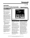
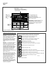
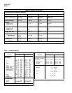
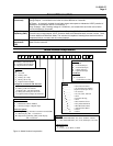
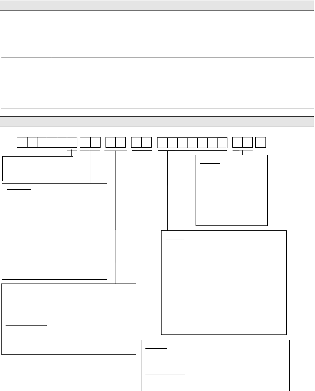
Model Number Interpretation
0
DC2 30
External Interface
0 _ = None
1 _ = RS422/485 ASCII / Modbus
2 _ = Auxiliary Output or Digital Input
Software Options
_ 0 =
Single Display (includes Accutune II on DC230B)
_ A =
Dual Display, MA, + Accutune II
_ B = Setpoint Programming (SPP), Dual Display,
MA, Accutune II
Manuals
0 _ = English
F _
= French (Europe)
G _
= German (Europe)
T _ = Italian (Europe)
S _ = Spanish (Europe)
Certificate
_ 0
= None
_ C
= Certificate of
Conformance (F3391)
Options
0 _ _ _ _ _ _ = 90 to 264 Vac Power
1 _ _ _ _ _ _ = 24 Vac/dc Power (Future)
(
requires Alarms plus IN 2)
_ 0 _ _ _ _ _
= UL and CE
_ A _ _ _ _ _
= UL, CE, CSA, and
FM
_ _ 0 _ _ _ _
= None
_ _ T _ _ _ _
= Customer ID Tag
_ _ _ 0 _ _ _
= None
_ _ _ P _ _ _
= Rear Terminal Cover
_ _ _ _ 0 _ _
= Gray Elastomer Bezel
_ _ _ _ B _ _
= Blue Elastomer Bezel
_ _ _ _ T _ _
= Tan Elastomer Bezel
_ _ _ _ _ 0 _
= Future
_ _ _ _ _ _ 0
= Future
B =
Basic Controller Model
L = Limit Controller Model
I =
Digital Indicator Model
Output #1
C _ = Current
E _ =
Relay, E-M
A _ =
Relay, SS 1 amp
S _ = Relay, SS 10 amp
T _ =Open Collector Output
Output #2 or Alarm #2 and Alarm #1
_ 0 =
No additional outputs or alarms
_ E = Relay, E-M and Alarm #1
_ A = Relay, SS 1 amp and Alarm #1
_ S = Relay, SS 10 amp and Alarm #1
_ T = Open Collector Output and Alarm #1
PV Input
1 _ = T/C, RTD,Radiamatic, mV, 0-5V, 0-20mA, 4-20mA
2_ = T/C, RTD,Radiamatic, mV, Volts,milliamps, 0-10 Volts
Optional Input 2
_ 0 = None
_ 1 = 0-5V, 1-5V, 0-20mA, 4-20mA
O =
None
Figure 4—Model Number Interpretation