


51-52-03-27
Page 7
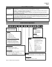
Specifications, continued
Design (continued)
Auxiliary Linear Output (Optional)
(Isolated)
21 mA dc maximum into a negative or positive grounded load or non-grounded
load of 0 to 500 ohms.
Output range can be set anywhere between 0 to 21 mA, and as direct or reverse
action. It can be configured to represent IN1, IN2, PV, Setpoint, LSP1, Deviation,
or Control output. The range of the auxiliary output, as a function of the selected
variable, can be scaled. This output can be used as a second current output for
current duplex outputs.
Resolution:
12 bits over 0 to 21 mA
Accuracy:
0.1% of full scale
Temperature Stability:
0.01% F.S./°C
Load Resistance:
0 to 500
Communications Interface (Optional)
RS422/485 ASCII
Baud Rate:
2400, 4800, 9600, or 19200 baud
Parity:
Odd or Even
Length of Link:
2000 ft. maximum
Link Characteristics:
Two-wire (half duplex), multi-drop RS422 ASCII , 31 drops
maximum.
RS422/485 Modbus RTU
Baud Rate:
2400, 4800, 9600, or 19200 baud selectable
Data Format:
Floating point or integer
Length of Link:
2000 ft. maximum
Link Characteristics:
Two-wire (half duplex), multi-drop Modbus RTU protocol,
31 drops maximum.
Setpoint Ramp/Soak Programming
(Optional)
Lets you configure 6 ramp and 6 soak segments to be stored for use as one
program or several small programs. You designate the beginning and end
segments to determine where the program is to start/stop allowing several small
programs. Each ramp segment can be configured to be run in Hours and Minutes
or degrees per minute. Soak segments can have a guaranteed soak deviation
which guarantees the time for each soak and will not start until the PV is reached.
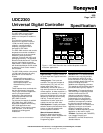
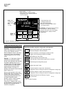
Digital Displays Vacuum fluorescent, Dual Displays
A four-character upper display dedicated to the process variable.
Alternate information displayed during configuration mode.
A six-character, alphanumeric lower display primarily shows key selected
operating parameters . Also provides guidance during controller configuration.
Indicators Alarm Relay Status (ALM 1 or 2)
Control Mode (A or M)
Temperature Units (F or C)
Remote Set Point or SP2 Active (R)
Control Relay Status (OUT 1 or 2)
Modes of Operation Manual (Available on Dual Display version only.)
Automatic with local setpoint
Automatic with remote setpoint
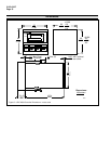
Dimensions See Figure 5.
Mounting Panel-mounted, 4.2-inch depth
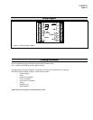
Wiring Connections Screw terminals on the rear of the case. (See Figure 6.)
Power Consumption 12 VA maximum (90 to 264 Vac) and (24 Vac/dc)
Power Inrush Current
10A maximum for 4 ms (under operating conditions)
CAUTION
When applying power to more than one UDC 2300, make sure that
sufficient power is supplied. Otherwise, the controllers may not start up normally
due to voltage drop from the inrush current.
Weight 1 kg (2.2 lbs.)