


7000 Bus Converter User Manual (version 1.2,Feb/2003, 7PH-006-10) --------------- 2
Table of Contents
1. Introduction..........................................................................................5
1.1 The 7000 series overview ..................................................5
1.2 Related Documentation for the 7000 Series.......................6
1.3 Common Features of the 7000 Series................................7
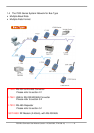
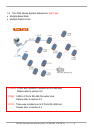
1.4 The 7000 Series System Network for Bus Type .................8
1.5 The 7000 Series System Network for Star Type .................9
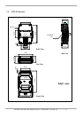
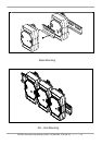
1.6 7000 Dimension................................................................. 11
2. I-7520/A/R/AR, PCI-7520AR, PCISA-7520R.......................................13
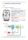
2.1 I-7520:............................................................................... 13
2.1.1 Pin Assignment and Specifications:....................................13
2.1.2 Block Diagram: ..................................................................13
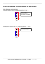
2.1.3 I-7520 is designed Termination resistor (120 Ohm) on board.14
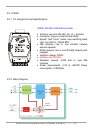
2.2 I-7520R: ............................................................................15
2.2.1 Pin Assignment and Specifications:...................................15
2.2.2 Block Diagram: .................................................................15
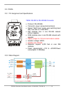
2.3 I-7520A: ............................................................................16
2.3.1 Pin Assignment and Specifications:...................................16
2.3.2 Block Diagram: .................................................................16
2.3.3 I-7520A has three different output type .............................17
2.3.4 I-7520A is designed Termination resistor (120 Ohm) on
board 17
2.4 I-7520AR:.........................................................................19
2.4.1 Pin Assignment and Specifications:...................................19
2.4.2 Block Diagram: .................................................................19
2.5 PCI-7520AR Pin Assignment and Specification:...............20
2.6 PCISA-7520R Pin Assignment and Specification: ............ 21
2.7 Basic Wire Connection for I-7520:....................................22
2.8 How to select 7520 / 7520R .............................................23
3. I-7560 / I-7561 / I-7563 ........................................................................27
3.1 I-7560 Pin Assignment and Specifications:....................... 28
3.1.1 The I-7560 System Network Configuration:.......................29
3.1.2 Block Diagram: .................................................................29
3.1.3 I-7560 Driver Installation ...................................................30
3.1.4 Verifying the Installation: ................................................... 34
3.1.5 Uninstalling the Device Driver ........................................... 37
3.2 I-7561 Pin Assignment and Specifications........................38