


7000 Bus Converter User Manual (version 1.2,Feb/2003, 7PH-006-10) --------------- 3
3.2.1 The I-7561 System Network Configuration:.......................39
3.2.2 The I-7561 Block Diagram: ...............................................39
3.2.3 I-7561 has three different Output type...............................40
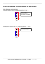
3.2.4 I-7561 is designed Termination resistor (120 Ohm) on board
40
3.2.5 I-7561 Driver Installation ...................................................42
3.2.6 Installation under Win2000/XP..........................................42
3.2.7 Install USB COM port........................................................45
3.2.8 Uninstall drivers ................................................................47
3.2.9 Installation under Win98/ME .............................................49
3.3 I-7563 Pin Assignment and Specifications:.......................54
3.3.1 The I-7563 System Network Configuration:.......................55
3.3.2 The I-7563 Block Diagram: ...............................................55
3.3.3 I-7563 Driver Installation ...................................................56
3.3.4 Verifying the Installation: ................................................... 60
3.3.5 Uninstalling the Device Driver ........................................... 63
4. I-7551 ..................................................................................................64
4.1 I-7551 Pin Assignment and Specifications:....................... 64
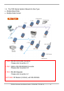
4.1.1 The I-7551 System Network Configuration:.......................65
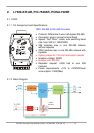
4.1.2 The I-7551 Block Diagram: ...............................................65
5. I-7510 / I-7510A / I-7510AR / I-7513....................................................66
5.1 I-7510:..............................................................................66
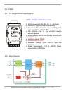
5.1.1 Pin Assignment and Specifications:...................................66
5.1.2 Block Diagram: .................................................................66
5.2 I-7510A: ........................................................................... 67
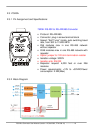
5.2.1 Pin Assignment and Specifications: .................................. 67
5.2.2 Block Diagram: .................................................................67
5.3 I-7510AR:.........................................................................68
5.3.1 Pin Assignment and Specifications:..................................68
5.3.2 System Network Configuration:......................................... 69
5.3.3 Block Diagram: .................................................................69
5.4 I-7513:..............................................................................70
5.4.1 Pin Assignment and Specifications:..................................70
5.4.2 System Network Configuration:........................................ 71
5.4.3 Block Diagram: ................................................................71
5.5 Basic Wire Connections for I-7510 ...................................72
6. 7000 RS-485 Networking ...................................................................73
6.1 Standard/Isolation Configuration ......................................73
6.2 PLC Networking Applications ...........................................77