


4
CONTENTS
Major features.................................................................. 4
Notes on settings and use ............................................. 4
Handling precautions ..................................................... 4
Installation in a rack........................................................ 4
Controls, indicators and connectors
Front panel ..................................................................... 5
Rear panel...................................................................... 6
Menu settings
Setting the menu ............................................................ 7
Sub menu....................................................................... 7
Storing menu settings in memory of this unit ................. 8
Recalling stored menu settings or factory default
settings........................................................................... 8
Entering characters ........................................................ 9
Menu contents.............................................................. 10
Others
Error output .................................................................. 16
Rear panel connectors ................................................. 18
Installing the power cable hook.................................... 18
Specifications ............................................................... 19
Supplement .................................................................. 21
MAJOR FEATURES
Ⅲ This unit converts SMPTE259M-standard SD digital serial signal
input to the SMPTE292M-standard (1080I or 720P) HD digital
serial signal for output.
Ⅲ Conversion modes are provided for input NTSC video signals
with an aspect ratio of 4:3 (standard), in the letter box format or
squeezed.
Ⅲ The delay time for video conversion is added to the embedded
audio to synchronize audio and video for output.
Ⅲ Input signal can be cropped (in the 4:3 mode, independently for
the left and right sides)
Ⅲ Background color can be set with hue, saturation and lightness.
Ⅲ It is possible to set or show the model name (up to 10
characters).
Ⅲ Each function can be set on the front panel with the LCD. The
unit can also be remote-controlled via the 9-pin connector on the
rear panel (RS-485 or RS-232C).
Ⅲ Menu settings can be saved in memory and loaded from
memory.
Four independent memories are provided to store menu settings.
Stored menu settings can be recalled as required.
Ⅲ Compact design allows this unit to be installed in a 1U EIA rack.
Ⅲ Color bar output possible.
Ⅲ External reference sync signal input connector
Ⅲ Three video/audio output connectors
Ⅲ Enhancer (contour correction), motion sensitivity, background
color, screen horizontal/vertical position and system phase can
be adjusted.
Ⅲ Error indication and alarm signal output function
Ⅲ Color correction function (option)
Ⅲ Variable enhancer (option)
NOTES ON SETTINGS
AND USE
● When the menu item <Reference> is set to [INPUT] and there is
no SD input signal, output video signals may be distorted. In this
case, input external sync signals and set <Reference> to [BB] or
[HD-SYNC]. (
੬
p. 10).
● When the menu item <Reference> is set to [BB] or [HD-SYNC]
and these external sync signals are not input or are incorrect,
output video signals may be distorted. In this case, system
phase cannot be assured. (
੬
p.10)
HANDLING
PRECAUTIONS
● Avoid using this unit in places subject to the following conditions:
– direct sunlight
– high humidity and dust
– vibrations
– extreme heat
These conditions can cause problems and may damage the unit.
● Influence of strong electric waves and magnetism
Noise may appear on the screen when used in places close to a
transmission antenna, or in places near transformers and motors
where strong magnetism can occur.
● This equipment is meant for use exclusively in commercial and
industrial applications. If used at home, it may cause
interference with radio and television reception.
● To save electricity, shut off the power when the unit is not in use.
● Use the supplied power cable for this unit.
● Do not place heavy objects such as a television monitor on top of
the unit. Doing so could cause damage or adversely affect
performance.
● Do not put any foreign objects into the unit.
● Do not disassemble the unit or try to modify it.
● Do not block the ventilation openings.
● Change the cooling fan about three years after installation of the
unit.
● When cleaning the cabinet, wipe it with soft cloth. Do not use
benzene or thinner as these may deform or discolor the cabinet
surface. To remove excessive dirt, clean the unit with a mild
detergent diluted with water, then wipe it with dry cloth.
● Do not use the unit in an environment exposed to gases
generated by chemicals or organic solvents.
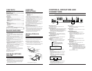
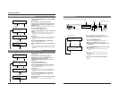
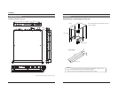
INSTALLATION IN A
RACK
This unit can be installed in EIA standard rack. Ensure
sufficient rack strength by attaching L-metal supports on
both sides of the rack on which you will place the unit.
1.
Detach the four feet on the base of the unit.
2.
Install the supplied rack mount brackets on both sides of
front panel using the four supplied screws (M4).
3.
Set this unit on the rack, and fix the rack mount brackets
onto the rack using the four supplied screws (M5).
1.
Foot
2.
Rack mount
bracket
2.
Rack mount
bracket
2.
Supplied
screw (M4) x 4
3.
Supplied
screw (M5) x 4
EIA rack
੬ See ‘‘Supplement’’ on page 21.
Optional software
For optional software, consult your JVC dealer. Using
it without formal procedures is illegal.
5
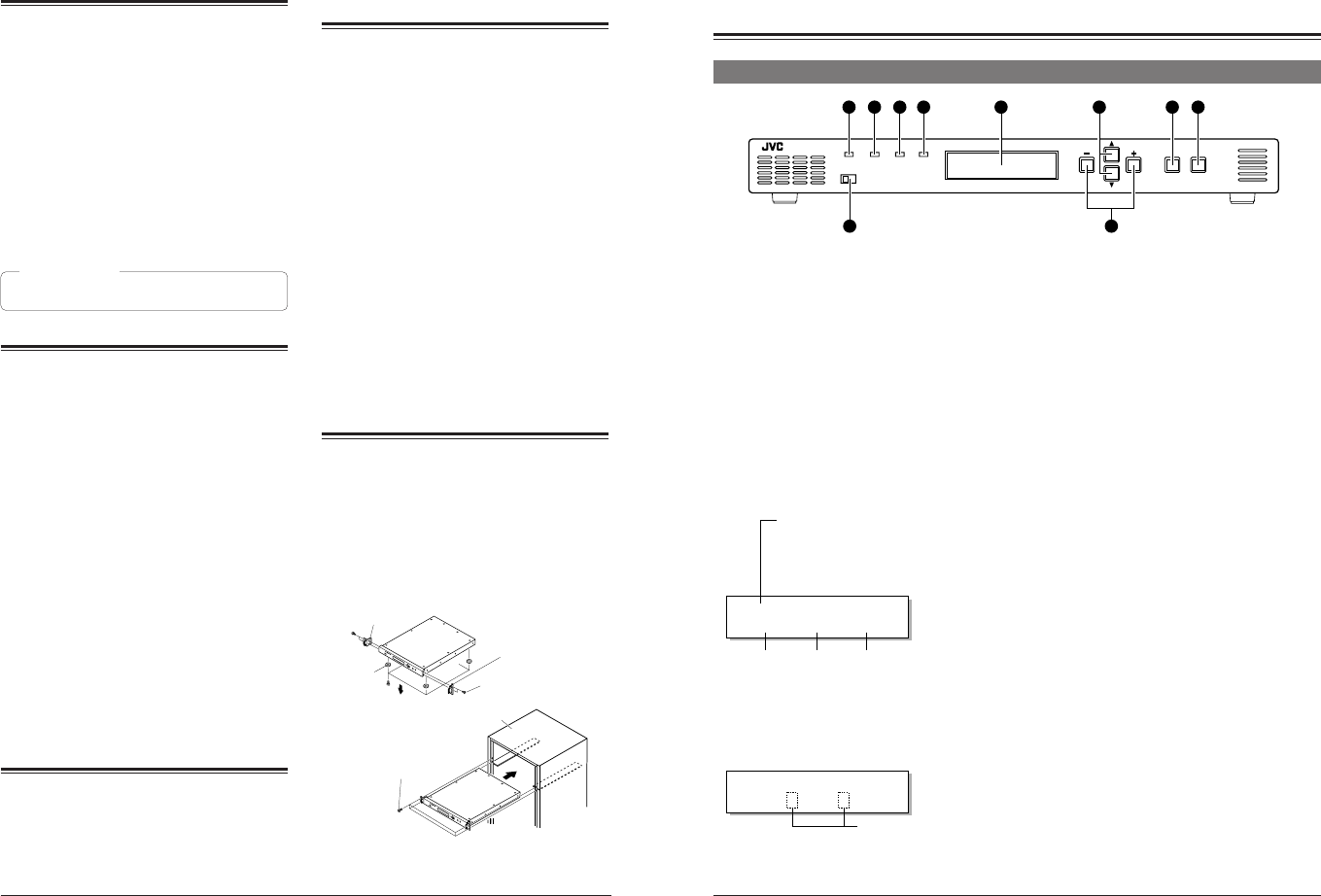
CONTROLS, INDICATORS AND
CONNECTORS
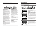
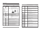
Front panel
1
[POWER] indicator
Lights green when power is supplied to this unit.
2
[STATUS] indicator
Normally lights green. Lights orange in the menu setting
mode, when the set value is changed or the set data is
transmitted to this unit. When the transmission is
complete, this indicator lights green again. When errors
occur in hardware, etc., this indicator lights red.
3
[INPUT] indicator
Normally lights green. When no signal is input, this
indicator lights orange. If there is an error in the input
signals, this indicator lights red.
4
[SYNC] indicator
Normally lights green. If a sync system-related error
occurs, this indicator lights red.
●For details on error indicators, see page 17.
5
Display
●When power is applied, the input/output or screen
display mode is shown. (Normal display mode)
POWER
LOCAL REMOTE
STATUS INPUT SYNC
MENU
ENTER ESC
BC-D2300U HDTV UP CONVERTER
21 3 4
610
5 7 8 9
BC–D2300
[ D1 |1080| 4:3]
Model name:
The model name can be set with the
menu (up to 10 characters). In the
remote mode, the remote ID number
(1 – 31) is shown following the model
name.
(e.g.) BC-D2300 ID: ⅪⅪ
Input form
Output form
Screen conversion mode
Memoranda:
●The screen conversion mode can be selected with
menu <Output Mode>.
੬ p. 10.
●Output form can be selected with menu <Output>.
੬ p. 10.
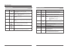
●When menu <Color Correction> is set to “ON” or
<Colorimetry> is set to “OFF”, the normal display
changes as follows.
●Press the
8
[ENTER/MENU] button to display the
item in the menu setting mode.
●If an error occurs in the normal display mode, a
description of the error is shown.
੬ p. 17.
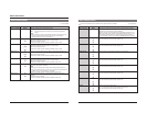
6
[+/–] button
Press this button to change the set value for a menu
item in the menu setting mode.
7 [
ᮡ
/
ᮢ
] button
Press this button to select the menu item in the menu
setting mode.
8
[ENTER/MENU] button
●In the normal display mode, press this button to
engage the menu setting mode.
●In the menu setting mode, press this button to enter
the set value for the following menu items. (? is
shown.)
Output Mode item
Output item
Profile Save item
Profile Load item
●Use to enter the sub menu. ([ENTER] is shown.)
9
[ESC] button
In the menu setting mode, press this button to restore
the normal display mode.
Memorandum:
●To use the menu setting, refer to pages 7 to 9.
0
[LOCAL/REMOTE] switch
Use to select LOCAL or REMOTE to operate this unit.
LOCAL : Set to this position to operate this unit with
the operation buttons on this unit.
REMOTE : Set to this position to remote-control this unit
via the [REMOTE IN] connector or [ALARM]
connector on the rear panel. Also, set to this
position to lock the front panel’s operation
buttons.
●The factory preset is LOCAL.
BC–D2300
[ D1 /1080/ 4:3]
Change