


6
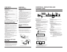
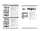
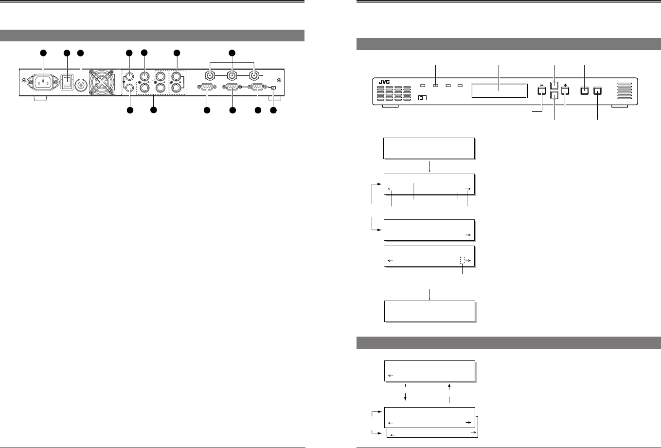
Rear panel
POWER
AC IN
ALARM
REMOTE-IN
REMOTE-OUT TERMINATE
OFF
ON
IN
OUT
SDI
1
23
HD SERIAL OUT
2
4
5
7
6
8 9
REF
Pb
Y
Pr
CVBS
CN1
ON
OFF
FUSE
1.6A(125V)
FUSE
96
5
1
96
5
1
96
5
1
1
3
10 11 12 13
LOOP
THROUGH
1
[AC IN] power input connector
Connect to an AC 120 V, 50 Hz/60 Hz power outlet with
the provided power cable. Attach the provided hook
beforehand.
੬ p. 18.
2
[POWER] switch
Use to turn the power on/off. When the power is turned
on, the indicators and display on the front panel light up.
3
Fuse holder
The fuse is built in. For fuse replacement, consult your
nearest JVC dealer.
4
[SDI IN] connector
Input a SMPTE259M standard SD digital serial signal
(NTSC). Compatible with embedded audio signals as
well. Embedded 20-bit digital audio with 48 kHz
sampling frequency can be input with 4 channels.
5
[SDI OUT] connector
Active through output of digital serial video/audio
signals input to the
4
[SDI IN] connector is possible.
6
[CVBS] connector
Input analog composite signals (NTSC). The optional
BC-D231 (D2/analog optional board) is required.
7
[Y/Pr/Pb] connectors
Input analog component signals (NTSC) to each
connector. The optional BC-D231 (D2/analog optional
board) is required.
Note:
●The [CVBS] and [Y/Pr/Pb] connectors are enabled
only when the BC-D231 optional board is installed.
For details, refer to the BC-D231 instruction manual.
8
[REF] external reference sync signal input
connectors (loop-through)
Input external reference sync signal. As these
connectors use a loop-through system, signals input to
one connector can be distributed from another connector
to the other equipment.
Memoranda:
●When signal distribution is not required or this unit is a
terminating device, terminate this unit with the external
75-ohm terminator.
●When the signals input to these connectors are used
as a reference sync signal, set the menu switch
<Reference> to “B.B” or “HD SYNC”.
੬ p. 10.
●When the signals input to these connectors are used
as a reference sync signal, synchronize the input
signal with the reference sync signal so that the V
sync is within ±300 µs.
9
[HD SERIAL OUT] HD digital serial output
connectors (3 lines)
Output SMPTE292M standard HD digital serial signals.
Output embedded digital audio signals with 20-bit
48 kHz sampling frequency as 4-channel signals.
0
[ALARM] connector ... D-sub 9-pin (male)
●This connector is an alarm output (relay contact)
connector. When a problem occurs with this unit, an
alarm signal is output.
●When menu switch <Remote Port> is set to “ALARM”,
remote operation via the RS-232C is possible.
To remote-control this unit via this connector, set the
[LOCAL/REMOTE] switch on the front panel to
“REMOTE”.
!
[REMOTE-IN] connector ... D-sub 9-pin (female)
This connector is the input connector for remote-control
device.
Connect this connector to a device conforming to the
RS-485 serial interface standard.
Memoranda:
●To use this connector, set menu switch <Remote Port>
to “REMOTE-IN”.
●Set the remote ID and remote transmission speed with
the menu switches.
●To remote-control this unit, set the [LOCAL/REMOTE]
switch on the front panel to “REMOTE”.
@
[REMOTE-OUT] connector ... D-sub 9-pin
(female)
Outputs the control signals input to the
!
[REMOTE-IN]
connector or
0
[ALARM] connector as signals conform-
ing to the RS-485 serial interface. Connect this connec-
tor to the [REMOTE IN] connector of another device.
Up to 31 devices can be connected in series with this
connection.
#
[TERMINATE] switch
This is the terminating switch for remote control signals.
With a series connection, set this switch to “ON” when
this unit is terminated or control signals from the
[ALARM] connector are received.
●The factory preset is “OFF”.
CONTROLS, INDICATORS AND CONNECTORS
7
Reference
INPUT
Out pu t M
LETT
o
E
d
R
e
BOX?
Output Mode
4:3
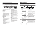
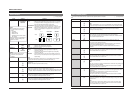
MENU SETTINGS
You can set various functions on the menu. Settings are stored and automatically activated whenever you turn on the power.
Up to four independent menu settings can be stored in the unit’s memory and recalled at any time. You can also restore the
default factory settings at any time. The menu is shown on the display.
1
Turn the power of this unit ON.
The model name, input/output and screen display mode are
shown on the display (normal mode).
2
Press the [ENTER/MENU] button to engage menu
setting mode.
●The display shows the menu. The current setting is shown.
3
Press the [
ᮢ
]
or [
ᮡ
] button to select the menu item.
4
Press the [+] or [–] button to change the setting.
Memoranda:
●When “[” is shown at the right of the display, press the
[+] button to change the setting. When “p“ is shown at the
left of the display, press the [–] button.
●When “?“ appears after the value you want to set, press the
[ENTER/MENU] button to enter the setting.
●When the setting is changed, the [STATUS] indicator lights
orange while the set data is transmitted to this unit. When the
transmission is complete, this indicator lights green.
Ⅵ Refer to the next page for details on how to store menu setting
contents in memory.
5
Press the [ESC] button to end menu setting.
●Your changes are stored in memory and the display returns to
normal.
Note:
If power is turned OFF without pressing the [ESC] button,
setting changes are not saved.
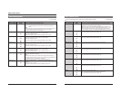
Setting the menu
POWER
LOCAL REMOTE
STATUS INPUT SYNC
MENU
ENTER ESC
BC-D2300U HDTV UP CONVERTER
[STATUS] indicator Display
3
[
ᮡ
] button
2
,
5
[ENTER/MENU] button
4
[–] button
3
[
ᮢ
] button
4
[+] button
6
[ESC] button
BC–D2300
[ D1 |1080| 4:3]
Normal display
Menu display
[
ᮢ
/
ᮡ
]
button
The [–] button
is effective.
Item
Setting
The [+] button
is effective.
Press the [ENTER/MENU]
button to enter the value.
The “?”goes out.
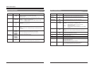
Normal display
Press the [ENTER/
MENU] button.
BC–D2300
[ D1 |1080| LB ]
Press the [ESC] button.
Sub menu
Wh i t e Leve l
0
0
C
ON ENTE
olor Co
[
rrecti
on
R]
Menu display
[ENTER/MENU] button
[ESC] button
Sub menu
[
ᮢ
/
ᮡ
]
button
Exact settings for variable enhancer (option), color correction
(option) and administration can be done on the sub menu.
1.
When setting the variable enhancer or color correction to ON,
or selecting administration, [ENTER] is shown on the display.
To enter the sub menu, press the [ENTER/MENU] button.
2.
Set each menu item in the same way as with the ordinary
menu.
3.
Press the [ESC] button to go to the upper menu by one.