


16
OTHERS
Error output
When an abnormality is detected, error notification is provided by LED illumination, error indication on the display and error
output to the [ALARM] connector.
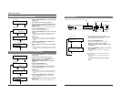
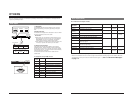
1. LED lighting
The [STATUS], [INPUT] or [SYNC] indicator on the front panel
lights orange (warning) or red (error), depending on the type of
error.
2. Display indication
The first line of the display shows a description of the error. When
the menu is displayed, errors are not shown.
Memoranda:
●With LOCAL, the error indication is shown when the error is
detected and goes out when the error is no longer detected.
With REMOTE, once an error is detected, the indication
remains (goes out when the switch is set to LOCAL).
●Error codes with 2 to 6 digits may be shown at the same time.
In this case, report the error codes to your JVC dealer.
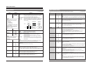
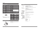
3. [Alarm] connector output
2-line alarm output terminals are provided for the rear panel’s
[ALARM] connector. Terminals A and B are short-circuited (relay
contact) when an error occurs or the power is turned off. Normally,
these terminals are open. (For open and short-circuited conditions,
refer to the table on the next page.)
The maximum rated value is 30 V 0.5 A for AC/DC with non-
inductive load.
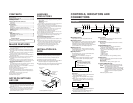
Pin assignment of the [ALARM] connector
D[1
108 4:3 ]0
Fan
Err
o
r
POWER
LOCALREMOTE
STATUS INPUT SYNC
MENU
ENTER ESC
BC-D2300U HDTV UP CONVERTER
STATUS INPUT SYNC
D[1
108 4:3 ]0
V. Da
t
a
E
rror03
POWER
AC IN
ALARM
REMOTE-IN
REMOTE-OUTTERMINATE
OFF
ON
LOOP
THROUGH
IN
OUT
SDI
1
23
HD SERIAL OUT
REF
Pb
Y
Pr
CVBS
CN1
ON
OFF
FUSE
1.6A(125V)
FUSE
96
5
1
96
5
1
96
5
1
ALARM
15
96
Pin
Name Contents
number
1 NC Unconnected
2 (RD) (Reception data for maintenance)
3 (SD) (Transmission data for maintenance)
4 ALARM2-B Alarm output 2 B terminal
5 GND Signal ground
6 ALARM2-A Alarm output 2 A terminal
7 ALARM1-A Alarm output 1 A terminal
8 ALARM1-B Alarm output 1 B terminal
9 NC Unconnected
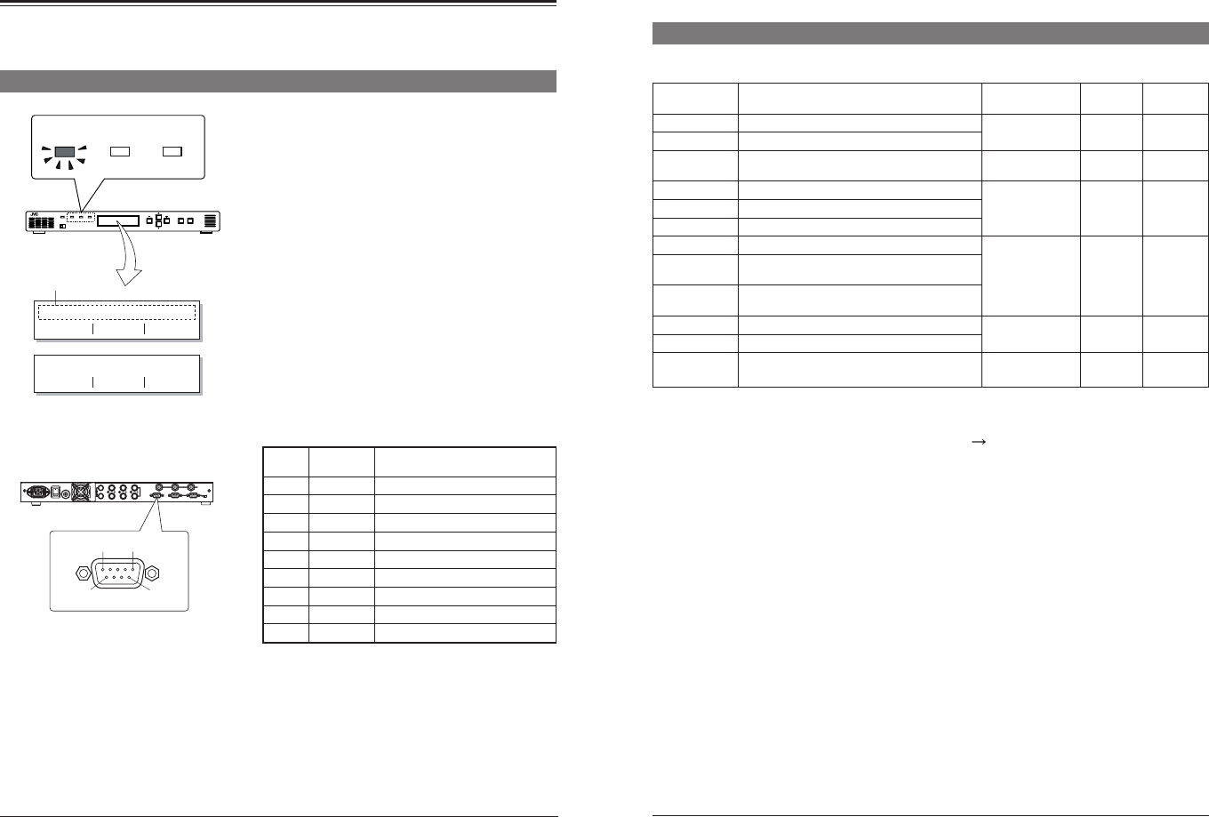
Front panel
Error indication
Display
Rear panel
17
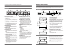
Error output (contd.)
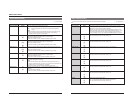
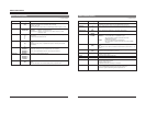
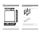
Error
Error contents LED ALARM 1 ALARM 2
indications
Power Error Abnormality in the power unit STATUS: Red Short- Open
Fan Error Abnormality in the fan motor
circuited
Data No-input No video and audio signal is input. INPUT: Orange Open Open
(warning)
V. Format Error Format error of the SDI input signals INPUT: Red Open Short-
V. Data Error Error of video data in the SDI input signal
circuited
A. Data Error Error of audio data in the SDI input signal
REF No-input No external sync signal is input (note) SYNC: Red Short- Open
SD Unlock Synchronization is not possible due to incorrect
circuited
video input signals
Ref Unlock Synchronization is not possible due to incorrect
external sync signal input
Comm Error Abnormal remote communication STATUS: Red Short- Open
Device Error Abnormality in the internal device
circuited
—— Power is turned off. —— Short- Short-
circuited circuited
Error indications and output contents
Note: When an incorrect external sync signal is input, the REF No-input error indication may be shown.
When an error indication is shown, check the input signal and connections according to type of error indicated. When this
unit malfunctions, consult your nearest JVC authorized service agent.
See "1.4 About Error Messages"
on page 1-3.